Home Pricing Help & Support Menu

Book your meeting with our
Sales team

Back to all articles

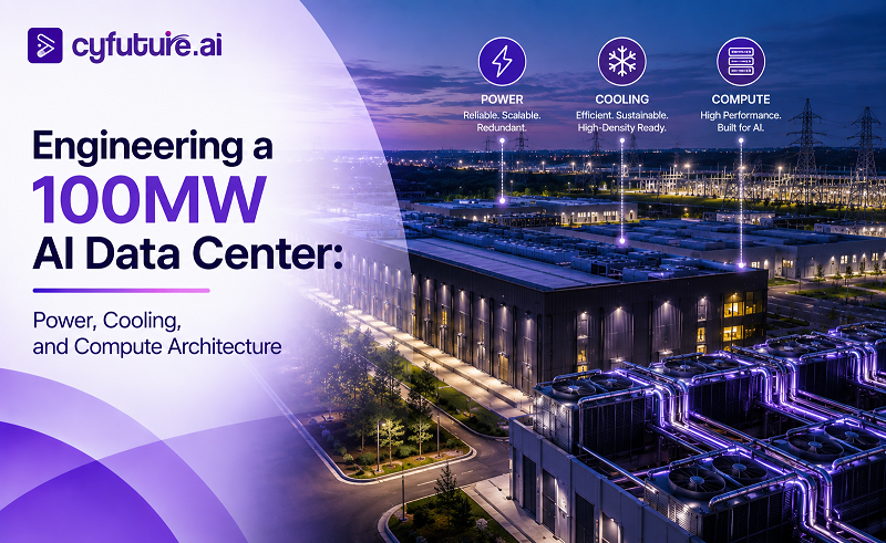
Engineering a 100MW AI Data Center: Power, Cooling, and Compute Architecture

H
Hemant 2026-09-01T17:50:46
Engineering a 100MW AI Data Center: Power, Cooling, and Compute Architecture


Why 100MW Is the New Baseline for AI Infrastructure

Five years ago, a 10MW data center was considered large for enterprise AI. Today, 100MW is the floor for serious hyperscale GPU infrastructure — and the engineering challenges that come with it are categorically different from anything built for traditional compute workloads. A 100MW AI data center isn't a bigger version of a cloud data center. It's a different class of physical plant, with power distribution, cooling, and networking architectures that need to be co-designed from the ground up.

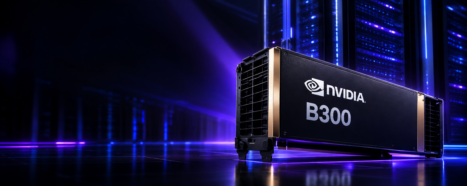
The driver is simple: modern GPU racks draw between 30 and 132 kW each. A single NVIDIA GB300 NVL72 rack — 72 B300 GPUs in a liquid-cooled chassis — operates at 120–132 kW. At that density, a 100MW facility houses 750–900 such racks. You cannot retrofit this into a conventional data center. You cannot cool it with air. You cannot power it from a single substation without careful engineering. Every decision cascades: power sizing determines cooling topology, cooling topology determines rack density, rack density determines networking architecture, networking determines storage latency budgets.

This article is a systems-level engineering guide. It covers how each of the five infrastructure layers — power, cooling, compute, networking, and storage — must be designed for a 100MW AI data center, the interdependencies between them, and the specific decisions that determine whether you achieve PUE 1.05 or PUE 1.4, whether your GPU utilization reaches 80% or stalls at 55%, and whether your interconnect fabric becomes the bottleneck for trillion-parameter training or remains invisible to workloads.

100MW
Total facility power — equivalent to powering ~80,000 Indian households continuously
750+
GB300 NVL72 racks at 132 kW each — 54,000+ B300 GPUs in a single facility
1.03–1.10
PUE achievable with DLC — vs 1.4–1.6 for legacy air-cooled hyperscale
Cyfuture AI 100MW liquid-cooled AI data center — DLC rack rows with direct-to-chip cooling pipes and purple LED-lit server hall
Cyfuture AI's liquid-cooled AI data center — DLC infrastructure supporting 100MW+ of GPU compute capacity. Direct-to-chip cooling loops maintain GPU junction temperatures within operating range at 1,400W per B300 GPU. Source: Cyfuture AI
Scope of This Guide

This guide covers the engineering architecture for a greenfield 100MW AI data center — the kind being planned or built by hyperscalers, national AI compute initiatives, and large GPU cloud providers. The principles apply equally to 20MW or 500MW facilities; the design patterns scale. Where India-specific considerations apply (grid quality, tariff structures, DPDP Act compliance, IndiaAI Mission infrastructure), they are called out explicitly.


The Five-Layer Architecture of a 100MW AI Data Center

A 100MW AI data center is best understood as five co-designed infrastructure layers. Each layer has its own engineering discipline, but their interdependencies are what make or break performance and efficiency at scale. Designing any layer in isolation produces a system where one layer becomes the bottleneck for all others.

Layer 1 — Power Infrastructure

Grid intake, primary substation, medium-voltage distribution, UPS systems, PDUs, and emergency generators. Sets the ceiling for everything else. Design target: 100MW IT load at 99.9999% availability with N+1 redundancy at every level from utility feed to rack PDU.

Layer 2 — Cooling Architecture

Direct Liquid Cooling (DLC) loops, rear-door heat exchangers, cooling distribution units (CDUs), chillers, dry coolers, cooling towers, and the facility's thermal management system. At 100MW, cooling is 10–25% of total facility power and the primary determinant of PUE.

Layer 3 — GPU Compute Architecture

GPU server selection, rack configuration, HGX/DGX baseboard topology, node density, GPU-to-CPU ratio, and the compute plane that workloads actually run on. The number, type, and arrangement of GPUs determines the facility's AI compute capacity in PFLOPS and its suitability for training versus inference workloads.

Layer 4 — AI Fabric & Networking

InfiniBand or Ethernet GPU fabric, NVLink within nodes, spine-leaf switching topology, front-end Ethernet for storage and management, and inter-rack interconnect. For distributed training at 100MW scale, networking is frequently the bottleneck that limits GPU utilization — more so than compute or memory.

Layer 5 — Storage & Data Architecture

Parallel file systems (Lustre, GPFS, WekaFS), NVMe-oF all-flash arrays, object storage tiers, checkpoint storage for training runs, and dataset staging. Storage throughput directly caps GPU utilization for data-intensive training workloads — an under-provisioned storage layer can idle 30–40% of compute.


Power Infrastructure Design

Power is the foundational constraint. Every other design decision derives from it. A 100MW AI data center requires careful engineering across five power sub-systems: utility intake, primary distribution, UPS, secondary distribution, and rack-level delivery — each with its own redundancy model and efficiency trade-off.

Utility Intake and Primary Substation

A 100MW facility draws power from the grid at medium or high voltage — typically 33kV, 66kV, or 132kV depending on the local grid and utility agreement. This requires a dedicated primary substation on-site, usually with dual utility feeds from separate grid injection points to eliminate single-point-of-failure at the utility level. In India, state DISCOM agreements for dedicated feeders at this scale require long-term power purchase agreements (PPAs) of 15–25 years and typically require advance infrastructure investments by the developer.

  • Primary voltage: 66kV or 132kV utility intake transformers stepping down to 11kV medium-voltage (MV) distribution ring
  • Redundancy: 2N at utility feed level — two independent utility connections, each capable of carrying 100% load
  • Transformer sizing: 125–130MVA total transformer capacity for 100MW IT load, accounting for losses and headroom
  • Protection systems: Automatic Transfer Switches (ATS) with sub-100ms switchover time between feeds

Power Domains and Modular Distribution

At 100MW scale, a monolithic power architecture is both an engineering risk and an operational liability. The industry standard is to divide the facility into independent 10MW power domains — each with its own MV/LV transformer, UPS system, generator, and distribution switchgear. This approach provides:

Fault Isolation

A power event in one 10MW domain affects only that domain's compute pods. The remaining 90MW of IT load continues uninterrupted. No single fault can bring down the full facility.

Phased Construction

Build 10MW domains as demand grows — commission domain 1 while domains 2–10 are under construction. Avoids stranded capital in a facility that's 20% loaded for its first two years.

Maintenance Windows

Planned maintenance on a single domain's UPS, transformers, or switchgear can be performed without requiring global maintenance windows that impact all customers.

Efficiency Optimization

UPS systems operate most efficiently at 80–90% load. Domain-level load balancing keeps each UPS in its efficiency sweet spot rather than running a large UPS at 30% load during early facility ramp.

UPS Architecture: Lithium-Ion vs VRLA

Uninterruptible Power Supply (UPS) systems at 100MW scale are a significant capital and operational decision. The industry is transitioning from traditional VRLA (valve-regulated lead-acid) battery UPS to lithium-ion (Li-ion) systems — driven by floor space, weight, maintenance, and total cost of ownership at scale.

Parameter VRLA UPS Li-Ion UPS Recommendation
Energy Density ~25–35 Wh/kg ~100–200 Wh/kg Li-Ion: 3–6× smaller footprint
Cycle Life 200–500 cycles 2,000–5,000 cycles Li-Ion: 8–12 year service life vs 3–5 yr
Operating Temp Range 20–25°C optimal –20°C to 60°C Li-Ion tolerates data center heat
Efficiency 94–96% 96–98% Li-Ion: 2–4% efficiency gain at scale
Capital Cost (per kWh) Lower upfront Higher upfront VRLA cheaper CapEx; Li-Ion better TCO
Maintenance Quarterly inspection Annual inspection Li-Ion: lower OpEx, fewer replacements
Thermal Runaway Risk Low Requires BMS Modern Li-Ion BMS mitigates risk
Runtime Target (AI DC) 5–10 min (generator ride-through) 5–10 min Same runtime target; Li-Ion achieves it in less space
UPS Runtime Reality for AI Workloads

AI data centers don't require long UPS runtime. The goal isn't to run on batteries for 30 minutes — it's to ride through the 10–15 seconds required for diesel generators to start and stabilize under load. Battery runtime targets of 5–10 minutes are standard. This means UPS battery banks can be sized tightly, and the real design question is efficiency and footprint, not capacity.

Generator Fleet

A 100MW AI data center requires a diesel generator (DG) fleet capable of sustaining full IT load for an extended outage. Generator sizing follows N+1 or 2N redundancy depending on the SLA tier, with typical units being 2.5MW–4MW per generator set. At 100MW, a typical N+1 generator fleet consists of 30–45 units grouped into clusters aligned with power domains.

Generator fuel storage for 48–72 hours of full-load operation at 100MW is a significant civil engineering consideration — approximately 500,000–750,000 litres of diesel in above-ground or below-ground tanks with secondary containment, fire suppression, and automated fuel transfer systems. Biofuel blends (HVO — hydrogenated vegetable oil) are increasingly used to reduce the carbon footprint of emergency generation.

Rack-Level Power Delivery

GPU racks at 100MW scale require high-density power distribution. NVIDIA GB300 NVL72 racks draw 120–132 kW — requiring dedicated 3-phase 415V feeds at 200–250A per rack. This means:

  • Overhead busway systems (Starline or equivalent) replacing traditional cabling for high-density row delivery
  • Intelligent PDUs (iPDUs) with per-outlet metering, remote switching, and environmental monitoring at every rack
  • Dual-corded servers with A+B feeds from separate PDU strings for rack-level redundancy
  • Power whips sized for 120kW+ loads — 4/0 AWG or larger cable or busway tap-offs of equivalent capacity

Cooling Architecture: Direct Liquid Cooling at Scale

Cooling is where 100MW AI data centers diverge most sharply from conventional compute infrastructure. Air cooling — still the dominant model for enterprise IT — becomes thermodynamically impossible above 20–25 kW per rack. NVIDIA B300 and GB300 NVL72 racks draw 120–132 kW. The physics are unambiguous: direct liquid cooling is not optional — it is mandatory architecture.

The good news is that liquid cooling, done right, is dramatically more efficient than air. DLC systems achieve PUE of 1.03–1.10 versus 1.40–1.60 for air-cooled hyperscale. At 100MW, a 0.35 difference in PUE equates to 35MW of additional cooling energy — roughly ₹215–275 Crore per year in electricity at Indian commercial tariffs. The business case for liquid cooling at this scale is overwhelming.

Cooling Distribution Unit (CDU) with stainless steel piping network — Cyfuture AI liquid-cooled AI data center direct-to-chip cooling infrastructure
Cooling Distribution Unit (CDU) architecture at Cyfuture AI's liquid-cooled AI data center. CDUs serve as heat exchangers between the facility cooling loop and the IT equipment loop, with quick-disconnect manifolds at each rack enabling hot-swap capability without facility shutdown. Source: Cyfuture AI

DLC Topology Options

Cooling Type Power Density Supported PUE Achievable Infrastructure Complexity GPU Compatibility
Air Cooling (CRAC/CRAH) Up to 20–25 kW/rack 1.35–1.60 Low H100, older generations only
Rear-Door Heat Exchanger (RDHx) 25–50 kW/rack 1.15–1.25 Medium Partial DLC — supplements air cooling
Direct-to-Chip Liquid Cooling 50–130 kW/rack 1.03–1.10 High B200, B300, H100 SXM (with DLC manifold)
Immersion Cooling (single-phase) Up to 200 kW/rack 1.02–1.05 Very High Requires custom hardware; limited NVIDIA support
Immersion Cooling (two-phase) 100–300 kW/rack 1.01–1.03 Highest Experimental; GWP concerns with fluorinerts

For NVIDIA B300 and GB300 NVL72 deployments, direct-to-chip DLC is the standard and the only approach that NVIDIA officially supports for warranty compliance on Blackwell Ultra hardware. NVIDIA's DLC manifold attaches to the server chassis and routes coolant directly through cold plates mounted on each GPU, CPU, and power module. The heated coolant exits at 40–55°C and is recirculated through facility cooling infrastructure.

The DLC Loop: From GPU to Cooling Tower

1

Server-Level Cold Plates

Coolant enters GPU cold plates at 28–32°C (supply). Each cold plate draws heat from the GPU die through a copper interface, heating the coolant to 40–55°C (return). NVIDIA's B300 cold plate design is integrated into the HGX baseboard — not an aftermarket addition. The cold plate loop is separate from any residual air handling within the chassis.

2

Rack-Level Manifold and Hose Connections

Each rack connects to facility piping via a manifold with quick-disconnect fittings. The manifold aggregates flow from all servers in the rack. A 132kW NVL72 rack requires coolant flow of approximately 30–40 litres per minute. Leak detection sensors at the manifold and at floor level are mandatory — a DLC leak in a live GPU rack is a high-severity incident.

3

Cooling Distribution Units (CDUs)

CDUs serve groups of 10–20 racks, acting as heat exchangers between the facility cooling loop and the IT equipment loop. They also provide flow control, pressure regulation, and leak isolation. A 100MW facility requires 50–100 CDUs depending on grouping strategy. CDUs are the boundary between the clean IT loop (deionized water) and the facility loop (treated water or glycol mixture).

4

Facility Cooling Plant: Chillers and Dry Coolers

The facility loop carries heat from CDUs to the central cooling plant. In mild climates (Indian winters, or high-altitude sites), free cooling via dry coolers can reject heat directly to the atmosphere without mechanical refrigeration — achieving near-zero cooling energy cost during suitable ambient conditions. When ambient temperatures exceed DLC supply temperature requirements, mechanical chillers engage. A 100MW facility requires 50–80MW of cooling plant capacity with N+1 chiller redundancy.

5

Heat Rejection: Cooling Towers and Dry Coolers

Final heat rejection to atmosphere happens at the cooling towers (evaporative, for highest efficiency) or dry coolers (closed-circuit, zero water consumption). A 100MW AI data center rejecting 95–105MW of total thermal load (IT load plus cooling plant losses) requires substantial heat rejection capacity. Water consumption for evaporative cooling at this scale is 50–100 million litres per year — a significant site selection factor in water-stressed Indian geographies.

Waste Heat Reuse: The 100MW Opportunity

DLC return water exits at 40–55°C — warm enough to be useful. A 100MW AI data center generates 95–105MW of waste heat continuously. This can supply district heating networks, industrial process heating, greenhouse agriculture, or absorption chillers for building cooling. In India, the economic case for waste heat reuse is emerging, with several large data center projects exploring tie-ups with industrial consumers near their sites.


GPU Compute Architecture

The compute layer of a 100MW AI data center is where infrastructure converts electricity into AI capability. GPU selection, node architecture, rack configuration, and the ratio between training and inference capacity are all design decisions that need to be made before the first foundation is poured — because they determine the power and cooling specifications for everything built around them.

GPU Node Architecture: HGX vs DGX vs NVL72

Node Type GPUs per Node Power Draw Memory per Node NVLink Bandwidth Best For
NVIDIA HGX B300 (8-GPU) 8 × B300 ~11 kW 2.3 TB HBM3e NVLink 5 — 1.8 TB/s per GPU Standard training node; flexible configuration
NVIDIA DGX B300 (8-GPU) 8 × B300 ~10.2 kW 2.3 TB HBM3e NVLink 5 — full mesh within node Managed NVIDIA stack; enterprise AI development
NVIDIA GB300 NVL36 (half-rack) 36 × B300 ~60–66 kW ~10.4 TB HBM3e 14.4 TB/s aggregate (36 GPU) Mid-scale inference; memory-bound LLM serving
NVIDIA GB300 NVL72 (full rack) 72 × B300 120–132 kW ~20.7 TB HBM3e 14.4 TB/s aggregate (72 GPU) Trillion-param training; frontier model inference

At 100MW scale, the mix of node types determines the facility's workload profile. A training-optimized facility leans toward NVL72 racks — maximum GPU memory per rack for fitting the largest models. An inference-optimized facility may use a mix of NVL36 and 8-GPU HGX nodes, balancing memory per rack against the number of independently schedulable inference endpoints. Most production facilities at 100MW run a blended architecture: 60–70% training-class racks and 30–40% inference-class configurations.

GPU-to-CPU Ratio

AI training and inference workloads are GPU-bound. CPUs in an AI data center are not the primary compute resource — they handle data preprocessing, orchestration, scheduling, and I/O. Overprovisioning CPU relative to GPU is one of the most common (and expensive) mistakes in first-generation AI data center designs.

GPU Compute Design Principles at 100MW Scale
GPU:CPU Ratio8:1 GPU-to-CPU ratio (e.g., 8 B300 GPUs per 2-socket AMD EPYC or Intel Xeon host) is standard for training. Inference endpoints may use 4:1. Over-provisioning CPU wastes power budget and rack space.
GPU Memory per RackNVL72 provides 20.7 TB HBM3e per rack. For a 405B parameter model in BF16, you need ~810 GB. NVL72 fits 25+ such models simultaneously — enabling high-concurrency serving without inter-rack communication.
Homogeneous vs HeterogeneousHomogeneous GPU fleets (all B300, all the same firmware) simplify scheduling, driver management, and support contracts. Heterogeneous fleets (B300 + H100 inference nodes) add operational complexity but allow cost optimization across workload tiers.
Training:Inference SplitA rough 70:30 split (by GPU count) between training and inference capacity is common in production AI cloud facilities. Inference workloads run continuously; training jobs are scheduled. This split maximizes overall GPU utilization.
Oversubscription PolicyInference GPU capacity can be logically oversubscribed up to 2–3× using MIG (Multi-Instance GPU) on H100 or time-sliced vGPU on Blackwell. This improves cost-per-token for smaller models without sacrificing latency SLAs for larger ones.
Spare GPU AllocationPlan 5–8% spare GPU allocation for hardware failures, burn-in testing of incoming units, and GPU health quarantine. At 54,000 GPUs, even a 0.5% daily failure rate means 270 units in various states of RMA or replacement at any given time.
Cyfuture AI · 100MW Liquid-Cooled AI Data Center · India · Enterprise GPU Cloud

Enterprise GPU Cloud Built on the Architecture in This Guide

Cyfuture AI's 100MW liquid-cooled AI data centers in Noida, Jaipur, and Raipur implement the DLC, NVLink fabric, and InfiniBand networking described here — available to enterprises via GPU as a Service with zero CapEx, INR billing, and DPDP Act compliance by architecture.

Direct Liquid Cooling InfiniBand GPU Fabric DPDP Compliant INR Billing + GST ISO 27001:2022 + SOC 2 Type II

AI Fabric and Networking Architecture

If the GPU is the engine and DLC is the cooling system, the network is the transmission. In distributed AI training at 100MW scale — where gradient synchronization happens across thousands of GPUs simultaneously — network bandwidth and latency directly determine GPU utilization. An undersized or poorly designed network fabric is the single most common reason that large AI training clusters run at 50–60% GPU utilization instead of 80–90%.

Three Distinct Network Planes

A production AI data center operates three logically separate network planes, each with distinct traffic characteristics, bandwidth requirements, and latency sensitivity:

GPU Compute Fabric (InfiniBand or RoCE)

All-reduce operations, gradient synchronization, and tensor parallelism communication. This is the highest-bandwidth, lowest-latency requirement — microsecond-scale latency, terabits-per-second aggregate bandwidth. NVIDIA Quantum-X800 InfiniBand (400 Gb/s per port, NDR) is the current standard. At 100MW scale with 54,000 B300 GPUs, the compute fabric requires 6,750+ switch ports at 400 Gb/s, organized in a fat-tree or DragonFly+ topology.

Storage Network (RoCE or NVMe-oF)

Dataset reads, checkpoint writes, and model weight distribution between storage and GPU memory. Latency tolerance is higher (milliseconds acceptable), but throughput requirements are extreme — a 54,000-GPU facility can demand 100–500 TB/s of aggregate storage throughput during large training runs. 100GbE to 400GbE Ethernet fabric connecting GPU nodes to all-flash storage arrays.

Management and OOB Network

BMC/IPMI out-of-band management, orchestration (Kubernetes), monitoring (Prometheus/Grafana), and user-facing API traffic. Separated from compute and storage planes to prevent management traffic from affecting GPU job performance. Typically 10GbE or 25GbE per node, with a dedicated management spine.

InfiniBand vs RoCE: The Core Architectural Choice

Parameter NVIDIA InfiniBand (NDR/XDR) RoCE v2 (Ethernet-based)
Max Port Bandwidth 400 Gb/s (NDR) / 800 Gb/s (XDR) 400 Gb/s (400GbE) / 800 Gb/s (800GbE)
Latency (MPI) 0.6–1.2 μs (hardware RDMA) 1.5–3.0 μs (with PFC/ECN)
Congestion Control Hardware-based (adaptive routing) Software PFC + ECN (tuning-intensive)
Reliability Lossless by design Requires careful PFC configuration to be lossless
NVIDIA Ecosystem Integration Native (NCCL, NVLink, Quantum-X800) Supported but not native
Switch Cost Premium (Quantum-X800 switches) Lower (commodity Ethernet silicon)
Operational Complexity Moderate — IB-specific skills needed Higher — PFC misconfiguration causes catastrophic congestion
Recommendation for AI Training Preferred for large clusters Viable with expert tuning

Fat-Tree Topology at 100MW Scale

The standard topology for large AI training fabrics is a 3-tier fat-tree: leaf switches (connecting GPU nodes), spine switches (connecting leaf tiers), and core switches (connecting spine tiers). At 100MW with 54,000 GPUs and 400 Gb/s per port:

  • Leaf layer: ~3,375 leaf switches, each connecting 16 GPU nodes and uplinked to spine with full bisection bandwidth
  • Spine layer: 200–400 spine switches providing non-blocking connectivity between leaf domains
  • Core layer: 20–40 core switches for inter-pod connectivity
  • Total switch ports: 500,000+ at 400 Gb/s — a significant capital and cabling plant investment
  • Cabling: Primarily active optical cables (AOC) or MPO fiber trunks for inter-switch links; Direct Attach Copper (DAC) for short hop leaf-to-server connections
The Networking Bottleneck: Where Most AI DCs Fail

The most common performance failure in large GPU clusters is not GPU failure — it is network congestion caused by insufficient bisection bandwidth or poorly tuned congestion control. All-reduce operations in distributed training generate synchronized, bursty traffic across all GPUs simultaneously. A fat-tree fabric with oversubscription ratios above 2:1 will experience congestion that reduces effective GPU utilization by 20–40%. Design for full bisection bandwidth at the GPU-to-leaf tier — this is non-negotiable for frontier model training.


Storage Architecture

Storage is the least-glamorous layer of an AI data center and the most frequently under-engineered. GPU memory is fast — 8 TB/s per B300. System DRAM is fast — ~1 TB/s aggregate per node. NVMe storage is slower by orders of magnitude. The gap between GPU memory bandwidth and storage bandwidth is the structural constraint that storage architects must bridge without creating a bottleneck that stalls the GPUs.

Four Storage Tiers in a 100MW AI Data Center

1

Hot Tier: GPU-Local NVMe (On-Node Storage)

Each GPU server node includes local NVMe SSDs (typically 4–16 × 7.68 TB or 15.36 TB Gen 4/5 NVMe) for scratch space, local checkpoint caching, and OS. Local NVMe provides 50–100 GB/s of sequential throughput per node — fast enough for local I/O but insufficient for shared dataset access across the full cluster. Used for temporary working sets and per-job scratch.

2

Warm Tier: All-Flash Parallel File System

The primary shared storage fabric — Lustre, IBM GPFS (Spectrum Scale), WekaFS, or BeeGFS on NVMe — provides the shared dataset access and checkpoint write path for active training jobs. Target: 1–5 TB/s aggregate throughput for a 100MW facility. This requires a purpose-built all-flash storage cluster of 50–200 high-density NVMe storage nodes, with a parallel file system distributing I/O across all nodes. WekaFS and Lustre are the dominant choices for GPU-scale deployments as of 2026.

3

Cold Tier: High-Density Object Storage

Trained model weights, archived checkpoints, datasets not currently in active training, and log archives live in an object storage tier — typically S3-compatible (Ceph, MinIO, or a managed object storage service). Throughput requirements are lower — 50–200 GB/s is usually sufficient — but capacity needs are large: 50–500 PB of raw object storage is typical for a 100MW AI facility at maturity. This tier uses high-density HDDs (20–30 TB HAMR/MAMR drives) rather than NVMe.

4

Checkpoint Burst Buffer

A dedicated high-speed buffer between GPU nodes and the parallel file system, designed to absorb the sudden peak I/O generated when training jobs checkpoint simultaneously. Without a burst buffer, checkpoint writes from 54,000 GPUs can saturate the parallel file system for minutes, stalling training. DDN IME (Infinite Memory Engine) and similar NVMe-based burst buffers absorb the spike and drain to the file system at sustained rates.


PUE, Energy, and Sustainability Architecture

Power Usage Effectiveness (PUE) is the ratio of total facility power to IT load power. A PUE of 1.0 would mean all power goes to compute — physically impossible. The question is how close you can get, and at 100MW the difference between PUE 1.05 and PUE 1.40 is 35MW of wasted power — approximately ₹215–275 Crore per year in unnecessary electricity cost.

PUE Target Cooling Technology Overhead Power at 100MW IT Load Annual Electricity Waste vs PUE 1.05
1.03 DLC + free cooling (mild climate) 3MW Baseline best-in-class
1.05 DLC + partial mechanical cooling 5MW ~₹12 Crore/year vs 1.03
1.10 DLC + chillers (standard) 10MW ~₹37 Crore/year vs 1.05
1.20 Hybrid air + partial DLC 20MW ~₹62 Crore/year vs 1.10
1.40 Traditional CRAC air cooling 40MW ~₹123 Crore/year vs 1.20
1.60 Older legacy air cooling 60MW ~₹123 Crore/year vs 1.40

Annual cost differences calculated at ₹8/kWh average Indian commercial tariff, 8,760 hours/year.

Renewable Energy Strategy at 100MW Scale

A 100MW AI data center consuming ~876 GWh per year is one of the largest electricity consumers in any Indian state. Sustainability commitments from enterprise customers — and regulatory direction from India's renewable energy targets — make a green energy strategy both an ESG requirement and an economic opportunity.

  • Power Purchase Agreements (PPAs): Direct long-term contracts with solar or wind developers provide electricity at ₹2.5–₹3.5/kWh — significantly below grid commercial tariffs of ₹7–9/kWh. A 100% renewable PPA reduces electricity cost by 50–60% at scale.
  • Captive Solar: Large data center campuses in India (especially Rajasthan, Andhra Pradesh, Tamil Nadu) can co-locate on-site solar generation for 20–30% of consumption, reducing grid dependence.
  • Open Access Power: Under India's open access framework, large consumers (above 1MW) can source power directly from generating companies, bypassing DISCOM cross-subsidy surcharges.
  • RECs (Renewable Energy Certificates): For locations where direct renewable sourcing is impractical, REC purchase provides a market mechanism for matching consumption with renewable generation.

Building 100MW AI Data Centers in India

Liquid-cooled GPU data center server hall — rows of DLC-equipped racks with purple lighting, built for India-hosted AI infrastructure
Cyfuture AI's India-hosted liquid-cooled AI data center server hall — purpose-built GPU infrastructure across Tier III+ facilities in Noida, Jaipur, and Raipur. Each facility implements DLC rack architecture, InfiniBand GPU fabric, and DPDP Act 2023-compliant data residency by design. Source: Cyfuture AI

India's AI infrastructure gap is closing fast, but the engineering challenges of building hyperscale GPU data centers in India have India-specific dimensions that differ from deployments in the US, Singapore, or Europe. Grid reliability, land acquisition, water availability, talent density, and regulatory requirements all shape how 100MW AI data centers get built and operated in the Indian context.

Grid Quality and Reliability

Indian grid reliability varies significantly by state and feeder. Voltage fluctuations, frequency deviations, and scheduled outages are more common than in mature markets. AI data centers require tighter input voltage tolerances than conventional compute — UPS systems must be sized for more frequent cycling. States with dedicated industrial feeders (Telangana, Tamil Nadu, Maharashtra, Haryana) have meaningfully better grid quality than rural or semi-urban locations.

Water Availability for Cooling

Evaporative cooling at 100MW consumes 50–100 million litres of water per year. Many Indian geographies — particularly Rajasthan and parts of Maharashtra — face water stress that makes this consumption environmentally and regulatorily problematic. DLC with dry coolers (closed-circuit, zero evaporative loss) is the preferred design for water-scarce Indian locations. Site selection should include water availability as a tier-1 constraint.

DPDP Act 2023 Compliance

India's Digital Personal Data Protection Act 2023 mandates data localisation for certain categories of personal data. AI workloads that process Indian user data — particularly in BFSI, healthcare, and government — must run on India-hosted infrastructure. This makes domestic 100MW AI data center capacity a regulatory requirement, not just a preference, for regulated industries.

IndiaAI Mission Infrastructure

The ₹10,371 crore IndiaAI Mission includes significant allocations for sovereign AI compute — government-funded GPU clusters hosted at Indian data centers. This creates a procurement pipeline for hyperscale AI infrastructure beyond purely commercial demand, accelerating the business case for 100MW-class facilities in India.

Skilled Talent and Supply Chain

India has a strong pool of electrical engineers, civil engineers, and IT infrastructure talent. However, GPU-specific operations expertise — NVIDIA firmware, NCCL tuning, InfiniBand fabric management, liquid cooling system operations — is scarce. Large AI data center operators in India are building dedicated GPU ops teams from scratch, a 12–24 month capability development effort that needs to start before the facility goes live.

Import Duties on GPU Hardware

GPU servers imported into India attract Basic Customs Duty (BCD) of 7.5–10% plus IGST of 18%, adding 25–30% to landed hardware cost. This is a significant CapEx differential versus US or Singapore deployments. Operators who achieve domestic sourcing through NVIDIA's Make-in-India partnerships or through exemptions under the National Data Center Policy avoid this surcharge — a material cost advantage.


How Cyfuture AI Implements This Architecture

Cyfuture AI's AI data centers in Noida, Jaipur, and Raipur are built on the architectural principles described in this guide — liquid-cooled GPU infrastructure, InfiniBand fabric, parallel NVMe storage, and India-native data residency. For enterprises that need access to hyperscale GPU compute without building their own 100MW facility, Cyfuture AI delivers this capacity via GPU as a Service.

Architecture Layer Cyfuture AI Implementation Enterprise Benefit
Power Infrastructure Tier III+ redundancy; dual utility feeds; Li-Ion UPS; N+1 generator fleet 99.9%+ uptime SLA; no single point of failure for your GPU workloads
Cooling Direct Liquid Cooling across all GPU racks; low-PUE operations; closed-loop CDUs B300/B200 GPU support; no air cooling constraints on rack density
GPU Compute NVIDIA B300, B200, AMD MI300X GPU fleets; HGX/DGX nodes Access to latest GPU generations without hardware purchase or import duty
Networking InfiniBand GPU fabric; 100GbE storage network; dedicated management plane Low-latency distributed training; NCCL-optimized all-reduce topology
Storage High-throughput parallel NVMe storage; S3-compatible object storage; checkpoint support Storage never becomes the GPU bottleneck; datasets available at cluster scale
Compliance India data residency; DPDP Act 2023 alignment; ISO 27001:2022 + SOC 2 Type II Regulatory compliance for BFSI, healthcare, and government AI workloads
Billing INR pricing; GST-compliant invoices; hourly, monthly, and reserved options No forex risk; predictable OpEx; fits Indian procurement processes

Design Decision Framework

Training frontier LLMs (>100B params)
NVL72 Racks + Full Bisection IB Maximum GPU memory per rack; NVLink 5 all-reduce within rack; fat-tree IB for cross-rack gradient sync
High-concurrency inference serving
HGX B300 + RoCE Storage 8-GPU nodes; MIG for multi-tenant isolation; NVMe-oF for fast weight loading; 100GbE per node
Mixed training + inference workloads
70% NVL72 + 30% HGX Separate scheduling pools; InfiniBand training fabric; RoCE inference fabric on shared physical infrastructure
Water-scarce Indian location (Rajasthan)
DLC + Dry Coolers (Zero Water) Closed-loop DLC; adiabatic pre-cooling; no evaporative towers; accept slight PUE penalty vs. cooling towers
Regulated workloads (BFSI, healthcare)
Bare Metal + DPDP Compliant DC Physical isolation; India data residency; ISO 27001:2022 + SOC 2 II; dedicated network segment
Budget-constrained new entrant
GPU as a Service (Cyfuture AI) Zero CapEx; access the full architecture via cloud; INR billing; scale as revenue justifies investment
Grid-unreliable location
Oversize UPS + Generator Fleet Li-Ion UPS with 15-min runtime; N+1 generator grouping per 5MW domain; automatic static transfer switches
Cyfuture AI · 20MW Liquid-Cooled AI Data Center · India-Hosted · Enterprise

Enterprise-Scale AI Infrastructure — Available Without the 100MW Commitment

Not every deployment needs 100MW. Cyfuture AI's 20MW liquid-cooled AI data center delivers the same DLC architecture, InfiniBand GPU fabric, and India data residency at an enterprise entry point — accessible in hours, billed in INR, DPDP compliant by design. The right infrastructure at the right scale, without the ₹30,000+ Crore capital commitment of a full hyperscale build.

Direct Liquid Cooling InfiniBand Fabric DPDP Compliant Zero CapEx · INR Billing ISO 27001:2022 + SOC 2 II

Frequently Asked Questions

At 100MW total facility power with a PUE of 1.05, approximately 95MW reaches IT load. NVIDIA GB300 NVL72 racks draw 120–132 kW each, yielding 720–790 racks. Each NVL72 rack contains 72 B300 GPUs, for a total of approximately 52,000–57,000 GPUs. In 8-GPU HGX B300 node configurations (drawing ~11 kW per node), the same 95MW IT load supports approximately 8,600 nodes or 68,800 GPUs. Most production facilities use a mix of rack types, yielding 50,000–65,000 B300-class GPUs at 100MW scale with DLC cooling.

The NVIDIA B300 GPU draws up to 1,400W per GPU. A full HGX B300 8-GPU baseboard draws approximately 11 kW; a GB300 NVL72 rack draws 120–132 kW. Air cooling becomes thermodynamically impractical above 20–25 kW per rack — standard data center air handling cannot remove heat at the density B300 hardware produces. NVIDIA mandates Direct Liquid Cooling (DLC) for B300 SXM deployments as a warranty condition. DLC cold plates are integrated into the HGX baseboard and route coolant directly across GPU dies. Air cooling alternatives are not supported and will result in thermal throttling and reduced GPU performance or hardware damage.

PUE (Power Usage Effectiveness) is total facility power divided by IT load power. A PUE of 1.0 would mean zero overhead — physically impossible. The target for a new 100MW AI data center with DLC should be 1.03–1.10. Legacy air-cooled hyperscale data centers typically achieve 1.4–1.6. At 100MW IT load, the difference between PUE 1.05 and PUE 1.40 is 35MW of additional cooling and overhead power — approximately ₹215–275 Crore per year in electricity cost at Indian commercial tariffs. DLC is the primary technology that enables sub-1.10 PUE at GPU rack densities above 30 kW/rack.

Two technologies dominate: NVIDIA InfiniBand (the preferred choice for large training clusters) and RoCE v2 (RDMA over Converged Ethernet, an alternative for organizations with existing Ethernet infrastructure). Within a single NVL72 rack or HGX node, NVLink 5 (1.8 TB/s bidirectional per GPU) handles intra-node communication — InfiniBand handles inter-node. The current generation standard is NVIDIA Quantum-X800 NDR InfiniBand at 400 Gb/s per port. At 100MW scale, the compute fabric requires thousands of 400 Gb/s switch ports organized in a fat-tree topology for non-blocking all-reduce operations during distributed training.

A greenfield 100MW AI data center in India requires CapEx across civil (land and building), power infrastructure, cooling, networking, and GPU hardware. Civil and power infrastructure alone runs ₹800–1,200 Crore for a Tier III facility at 100MW. GPU hardware — 54,000 B300-class GPUs at ~₹44.5 Lakh each, plus landed import duties — adds ₹28,000–32,000 Crore. Cooling, networking, storage, and software bring the full facility cost to ₹30,000–35,000 Crore or more. Annual OpEx at ₹7–9/kWh electricity cost runs ₹600–800 Crore for power alone. This scale of investment is why most enterprises access hyperscale AI compute through GPU cloud providers rather than building their own facilities.

A 100MW AI data center requires a four-tier storage architecture: (1) GPU-local NVMe SSD scratch storage on each server node for working sets and local checkpoints; (2) a high-throughput all-flash parallel file system (Lustre, WekaFS, or GPFS) providing 1–5 TB/s aggregate shared throughput for active training datasets; (3) S3-compatible object storage for trained model weights, archived datasets, and cold data — typically 50–500 PB capacity using high-density HDDs; and (4) a checkpoint burst buffer (DDN IME or equivalent) to absorb peak I/O from simultaneous checkpointing across tens of thousands of GPUs without stalling training runs.

The industry standard is 2N redundancy at the utility feed level (two independent grid connections, each capable of carrying 100% load) and N+1 at UPS and generator levels. At 100MW scale, the facility is divided into 10 independent 10MW power domains — each with its own transformer, UPS, and generator group. A power event in one domain affects only that domain's compute; the remaining 90MW continues uninterrupted. Generator fleets size at N+1 per domain, with fuel storage for 48–72 hours of full-load operation. Automatic Transfer Switch (ATS) systems provide sub-100ms switchover between utility feeds and between utility and generator.

India's Digital Personal Data Protection Act 2023 mandates that certain categories of personal data of Indian citizens must be processed and stored within India. For AI workloads that train on or infer from data containing Indian personal data — particularly in BFSI, healthcare, e-commerce, and government applications — this creates a legal requirement to use India-hosted infrastructure. This cannot be satisfied by routing traffic through Indian points-of-presence of international cloud providers if actual data processing occurs outside India. Purpose-built Indian AI data centers with verifiable data residency — like Cyfuture AI's Noida, Jaipur, and Raipur facilities — satisfy this requirement by architecture, not by contractual workaround.

Both deliver RDMA (Remote Direct Memory Access) for GPU-to-GPU communication with latency far below TCP/IP Ethernet. InfiniBand (NVIDIA Quantum-X800 NDR at 400 Gb/s) is purpose-built for HPC/AI, lossless by design, with native RDMA and hardware-based congestion control. MPI and NCCL all-reduce latency over IB is 0.6–1.2 microseconds. RoCE v2 runs RDMA semantics over standard Ethernet hardware — lower switch cost, but requires careful PFC (Priority Flow Control) and ECN configuration to achieve lossless operation. RoCE MPI latency is 1.5–3.0 microseconds with correct tuning; misconfigured RoCE causes catastrophic congestion during synchronized all-reduce. For frontier model training at scale, InfiniBand is the safer architectural choice.

Yes — through GPU as a Service providers like Cyfuture AI, which operate liquid-cooled, InfiniBand-connected AI data centers in India and make them available via hourly, monthly, or reserved billing. Enterprises access NVIDIA B300, B200, and AMD MI300X GPU clusters with the full architecture described in this guide — DLC cooling, InfiniBand fabric, parallel NVMe storage — without the ₹30,000+ Crore CapEx of building a 100MW facility. INR billing, DPDP Act compliance, ISO 27001:2022 and SOC 2 Type II certification, and deployment in hours rather than years make GPU cloud the practical path for the vast majority of Indian enterprises needing frontier AI compute.

H
Written By
Hemant Pal
Assistant Manager· AI Infrastructure & Data Center Architecture

Hemant Pal covers AI data center engineering, GPU cloud infrastructure, and enterprise AI compute strategy for Cyfuture AI. He specialises in making complex infrastructure architecture — power distribution, liquid cooling systems, InfiniBand networking, and GPU cluster design — accessible to CTOs, infrastructure architects, and AI engineering teams planning or evaluating large-scale compute deployments in India.

Related Articles