

 IND
IND UAE
UAE SA
SA


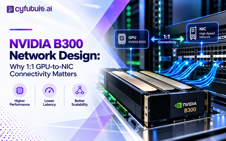
NVIDIA B300 Network Design: When the Bottleneck Isn't the GPU
Picture a cluster of NVIDIA B300 GPUs running a multi-node pre-training job. Every accelerator has 288 GB of HBM3e on board. Every accelerator is rated for petaflops of FP4 and FP8 throughput. On paper, the compute budget looks generous. Yet step time keeps drifting upward, GPU utilization oscillates between 40% and 90% instead of holding steady, and the all-reduce phase of every training step takes longer than the forward and backward passes combined.
Nobody touched the model. Nobody changed the batch size. The GPUs did not get slower. What changed is that the cluster scaled past the point where a single node's internal bandwidth could absorb the communication pattern, and the job started depending on the network fabric between nodes — the NICs, the cables, the switches, and the paths between them.
This is the starting point for NVIDIA B300 network design: once accelerators reach B300-class memory capacity and interconnect speed, the network stops being a supporting utility and becomes part of the compute architecture itself. The central design question this article works through is 1:1 GPU-to-NIC connectivity — what it means, why it's used, and why it is one input into a balanced fabric rather than a guarantee of performance on its own.
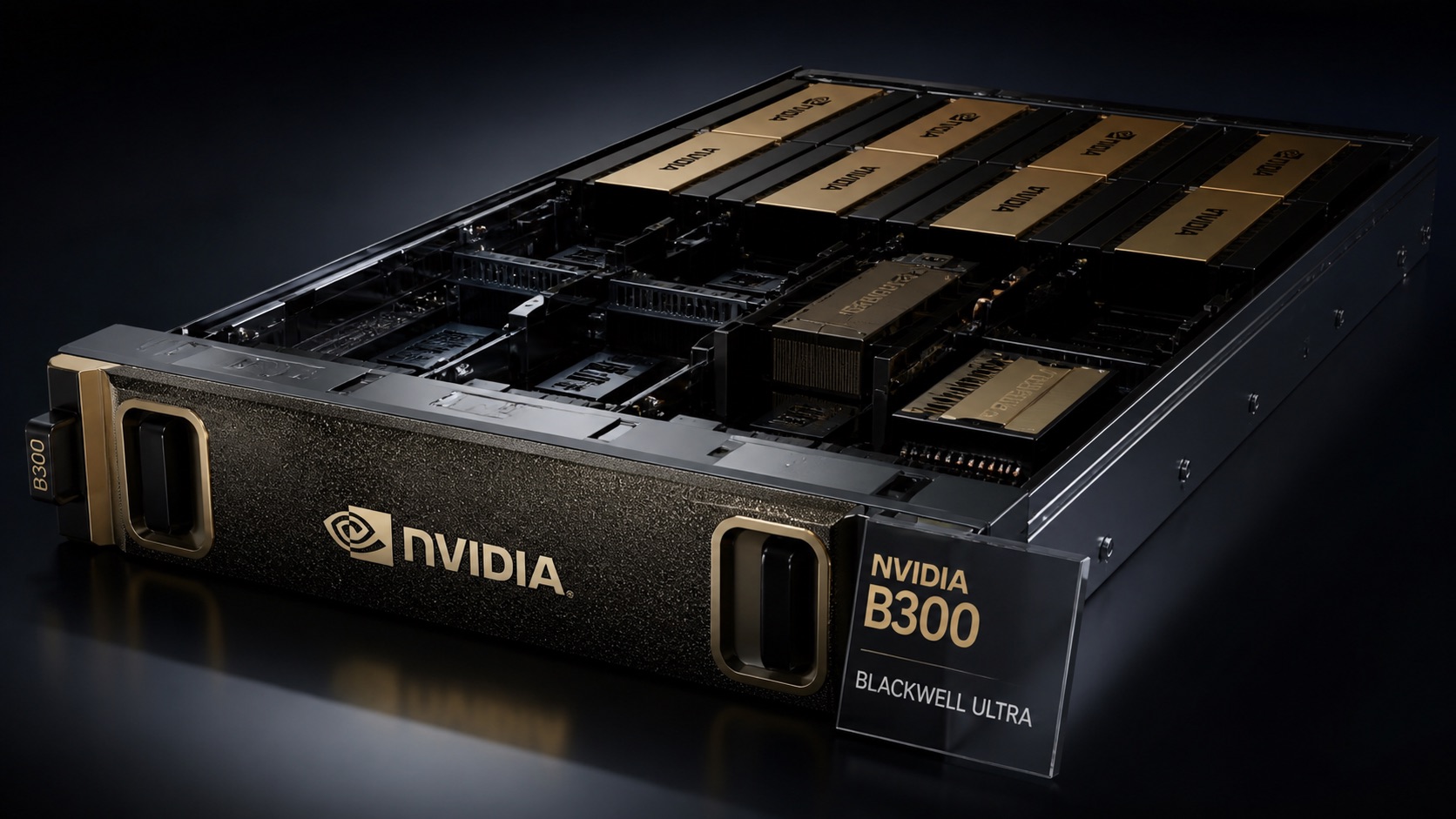
When accelerators become faster and carry more memory, the network around them becomes part of the compute architecture. That single idea drives every decision covered below — from GPU-to-NIC affinity to leaf-spine oversubscription to why a cluster can be "1:1" at the edge and still be blocking at the core.
Why Networking Has Become Part of GPU Architecture
Conventional enterprise applications mostly move data along a simple path: application tier to database tier to storage, with network traffic flowing north-south between clients and servers. Distributed AI training and inference invert this. The dominant traffic pattern is east-west — GPU to GPU, node to node — driven by parallelism strategies that split a model or a batch across many accelerators:
- Data parallelism — every GPU holds a full model replica and trains on a different shard of the batch, then synchronizes gradients through an all-reduce.
- Tensor parallelism — individual layers are split across GPUs, requiring activation and gradient exchange on nearly every forward and backward step.
- Pipeline parallelism — different layers live on different GPUs, and activations move forward while gradients move backward through the pipeline.
Each of these relies on collective operations — all-reduce, all-gather, reduce-scatter, broadcast — that must complete before the next compute step can begin. A conventional application can often tolerate a slow network call somewhere in the request path. A distributed training step cannot: every GPU idles until the collective finishes, because the next matrix multiplication depends on synchronized weights or gradients.
The practical result is that the data path for an AI cluster looks less like application → database → network and more like GPU ↔ GPU ↔ NIC ↔ switch ↔ NIC ↔ GPU, repeated across every node in the job. That's the reason NVIDIA B300 network design has to be treated as a first-class architectural discipline rather than a generic data-center networking exercise.
What 1:1 GPU-to-NIC Connectivity Actually Means
At the simplest conceptual level, 1:1 GPU-to-NIC connectivity means each GPU in a server is paired with a dedicated network interface — rather than several GPUs sharing one NIC and competing for its queue and bandwidth.
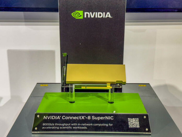
In practice, the term collapses several distinct engineering decisions that are worth separating:
- One physical NIC per GPU — a dedicated adapter card or SuperNIC assigned to a single accelerator.
- One NIC port per GPU — a multi-port NIC where each port, rather than each card, maps to a GPU.
- Logical device mapping — how the operating system, driver, and communication library (such as NCCL) present the GPU-to-NIC relationship to software, which may or may not mirror the physical wiring exactly.
- Dedicated vs shared NIC resources — whether a NIC's queues, buffers, and bandwidth are reserved for one GPU or time-shared across several.
These distinctions matter because "1:1" on a spec sheet can describe any of them. A server with eight GPUs and eight NIC ports satisfies a narrow definition of 1:1 even if those eight ports live on four physical dual-port cards with shared PCIe lanes — which is a materially different bandwidth and locality story than eight independent single-port adapters, each on its own PCIe slot.
In a high-performance AI cluster, the GPU is only one part of the data path. If each accelerator cannot obtain the network bandwidth and locality it requires, expensive compute capacity can sit idle waiting on communication — regardless of how fast the GPU itself is.
GPU-to-NIC Affinity — Why Physical Placement Matters
GPU-to-NIC affinity and GPU-to-NIC bandwidth are related but not identical. A GPU can technically reach a NIC that exists somewhere in the server and still get a worse path than a GPU whose NIC sits on the same PCIe switch and the same NUMA node.

The variables that determine whether a "1:1" pairing is actually efficient include:
- PCIe locality — whether GPU and NIC sit under the same PCIe switch/root complex, avoiding a hop across the inter-socket interconnect.
- NUMA and socket affinity — cross-socket memory and DMA access typically carries higher latency and lower effective bandwidth than same-socket access.
- DMA path — how directly the NIC can read from or write to GPU memory without traversing an inefficient route through system memory or a remote socket.
- Topology-aware software — whether the driver stack, container runtime, and communication library (NCCL and equivalents) are actually configured to select the local NIC for a given GPU rather than defaulting to whichever adapter is available.
Operators typically confirm this with topology-inspection tools such as nvidia-smi topo -m and lspci, cross-checked against NCCL's own topology detection output — not as a CLI tutorial, but as a way to verify that the physical wiring, the PCIe hierarchy, and what the software believes about the hierarchy all agree.
RDMA and GPUDirect RDMA — Moving Data Without the CPU as Middleman
RDMA (Remote Direct Memory Access) lets a network adapter read from or write to memory on a remote system without routing every transfer through the host CPU. For collective communication at scale, this matters because CPU-mediated copies add latency and consume cycles that would otherwise go to orchestration and scheduling work — overhead that compounds across thousands of small messages in a collective operation.
GPUDirect RDMA extends this idea one layer further: on compatible hardware, drivers, and network stacks, a NIC can transfer data directly to and from GPU memory, bypassing a copy through host system memory. This is significant for B300 clusters specifically because larger per-GPU memory (288 GB) means collective operations can involve larger payloads — all-reduce over bigger gradient tensors, all-gather over larger KV caches in inference — so the cost of an inefficient copy path scales with that memory growth.
GPUDirect RDMA is not something a B300 deployment gets simply by owning B300 GPUs. It depends on NIC hardware support, driver versions, kernel modules, and a network stack (InfiniBand or RoCE-capable Ethernet) that is actually configured for it end to end. Verifying this in a candidate deployment is a legitimate procurement question, not an assumption.
InfiniBand vs Ethernet/RoCE for B300 AI Clusters
Both fabrics can carry RDMA traffic for GPU clusters, and the right choice depends on scale, existing operational skillsets, and ecosystem requirements — not a universal winner.
| Factor | InfiniBand | High-Speed Ethernet (RoCE) |
|---|---|---|
| Ecosystem | NVIDIA Quantum switches; purpose-built for HPC/AI | Broad multi-vendor Ethernet ecosystem |
| RDMA support | Native to the architecture | Via RoCEv2, layered on Ethernet |
| Congestion management | Credit-based flow control; specialized in-fabric handling | Requires lossless-fabric tuning (PFC/ECN) or a purpose-built stack such as Spectrum-X |
| Latency profile | Very low, consistent under contention | Depends heavily on switch design and configuration quality |
| Operational model | Specialized skillset, common in HPC/AI shops | Familiar to broader enterprise networking teams |
| Typical role today | Backend GPU-to-GPU fabric in large training clusters | Growing role in AI fabrics via NVIDIA Spectrum-X and RoCE |
InfiniBand remains a common choice for the backend fabric in large-scale AI/HPC clusters precisely because native RDMA and hardware-level congestion control reduce the tuning burden. Ethernet-based fabrics — particularly NVIDIA Spectrum-X, purpose-built for AI with RoCE — are an increasingly credible alternative, especially for organizations that want to standardize on Ethernet operations across their AI and general-purpose infrastructure. Neither is universally correct; the decision should follow cluster scale, target workloads, and the team's existing operational depth.
What Happens When the GPU-to-NIC Ratio Isn't Balanced?
Contrast two edge configurations for the same four-GPU group:
When several GPUs share a single NIC, potential consequences include queueing delay on the shared adapter, bandwidth contention during simultaneous collective calls, less predictable per-GPU latency, and — in workloads with heavy synchronization — a lower effective scaling efficiency as GPU count increases. None of this is automatic or universal. The actual impact depends on the workload's communication intensity, the NIC's total bandwidth relative to combined GPU demand, the switch fabric behind it, and how well the software stack schedules traffic. A lightly synchronized inference workload may tolerate a shared NIC without issue; a tightly synchronized multi-node training run with frequent all-reduce calls is far more sensitive to it.
1:1 GPU-to-NIC Is Not the Same as a Non-Blocking Network
This is one of the more important distinctions in B300 network design: a server can be wired 1:1 at the edge and still sit behind an oversubscribed fabric.
In the left example, the edge mapping is a clean 1:1 GPU-to-NIC pairing — yet the leaf switch forwards eight downstream links onto only four upstream links, a 2:1 oversubscription at that layer. Traffic that never leaves the leaf switch is unaffected; traffic that must cross the spine to reach GPUs on another leaf competes for half the available uplink capacity. The right example keeps the same 1:1 edge mapping but preserves full uplink bandwidth, so cross-leaf collective traffic doesn't queue behind an artificially narrow chokepoint.
The takeaway: 1:1 GPU-to-NIC connectivity describes the edge of the network. Blocking vs non-blocking describes the entire path — port speeds, uplink counts, switch radix, and topology, evaluated against the traffic pattern the workload actually generates. Calling every leaf-spine design "non-blocking" without checking the uplink ratio for the workload's actual east-west volume is one of the more common oversimplifications in AI cluster network design.
The B300 Cluster Data Path — End to End
A single gradient exchange between two GPUs on different nodes traverses a long chain, and latency or bandwidth loss can occur at any hop:
GPU Memory → PCIe / Local Interconnect
Data leaves GPU HBM3e and moves across the local interconnect (PCIe, or NVLink/NVSwitch for intra-node GPU-to-GPU hops) toward the NIC.
NIC → Top-of-Rack / Leaf Switch
The NIC transmits over its network port — ideally via RDMA/GPUDirect RDMA — to the leaf switch it's physically connected to.
Leaf → Spine Fabric
If the destination GPU sits on a different leaf, traffic crosses uplinks into the spine layer — the point where oversubscription, if present, has its effect.
Spine → Remote Leaf → NIC → GPU Memory
The reverse path delivers data to the destination NIC and, via GPUDirect RDMA where supported, directly into the remote GPU's memory.
Networking and Collective Communication
Distributed frameworks coordinate GPUs through collective operations — AllReduce to sum and distribute gradients, AllGather to assemble sharded tensors, ReduceScatter to combine and partition results, and Broadcast to distribute a value from one rank to all others. NVIDIA's NCCL library is the most common implementation used with CUDA-based training stacks, and it performs topology detection — reading PCIe, NVLink, and NIC placement — to choose transport paths and ring/tree algorithms that match the physical layout. This is precisely why GPU-to-NIC affinity from earlier sections matters in practice: if NCCL's topology view doesn't match the real hardware locality (for example, because of a misconfigured container runtime), it can select a communication pattern that undershoots the fabric's actual capability. NCCL is the dominant option in the NVIDIA/CUDA ecosystem but not the only collective communication library in use across the broader distributed-training landscape.
Why GPU Utilization Can Fall When Networking Is Poor
Network bottleneck → communication delay → GPU wait time → lower effective utilization → longer training or inference runtime → higher cost per useful unit of compute. A GPU can be architecturally powerful and still be economically underutilized, because it spends real wall-clock time waiting on a collective operation to complete rather than computing.
This is where B300 network design connects directly to training economics. Poor network scaling shows up as more communication time relative to compute time per step, which lowers effective GPU utilization, which lengthens the total runtime of a training job, which increases energy consumption and infrastructure time billed against that job, which raises the cost per training milestone reached. For inference-heavy deployments, the same chain affects throughput, concurrency, and — while it is only one factor among several — cost per token served, since more GPU time spent idle on network waits reduces the useful requests a given GPU fleet can serve per hour.
Building High-Density B300 AI Infrastructure?
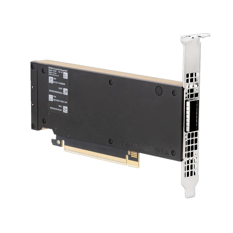
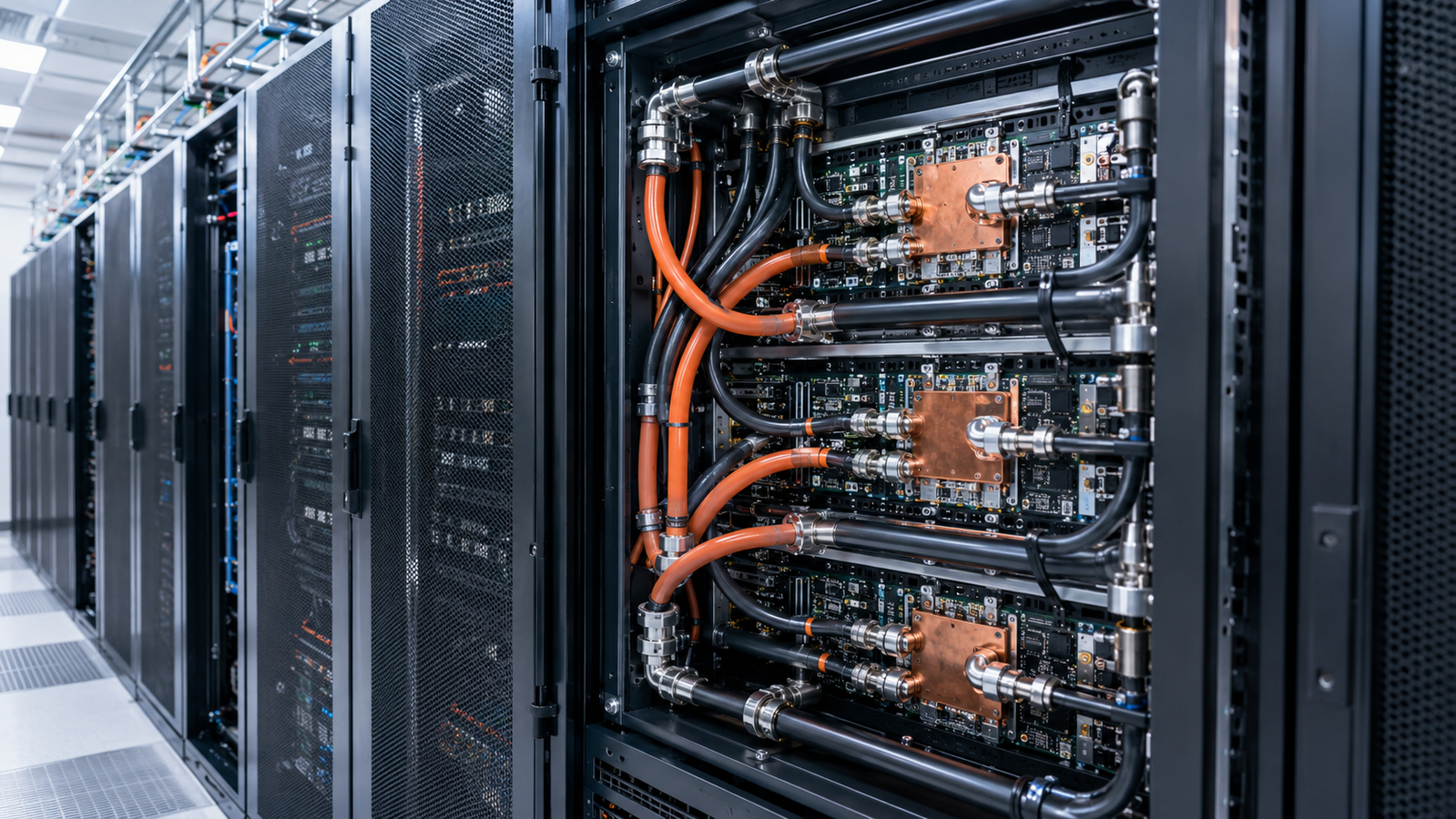
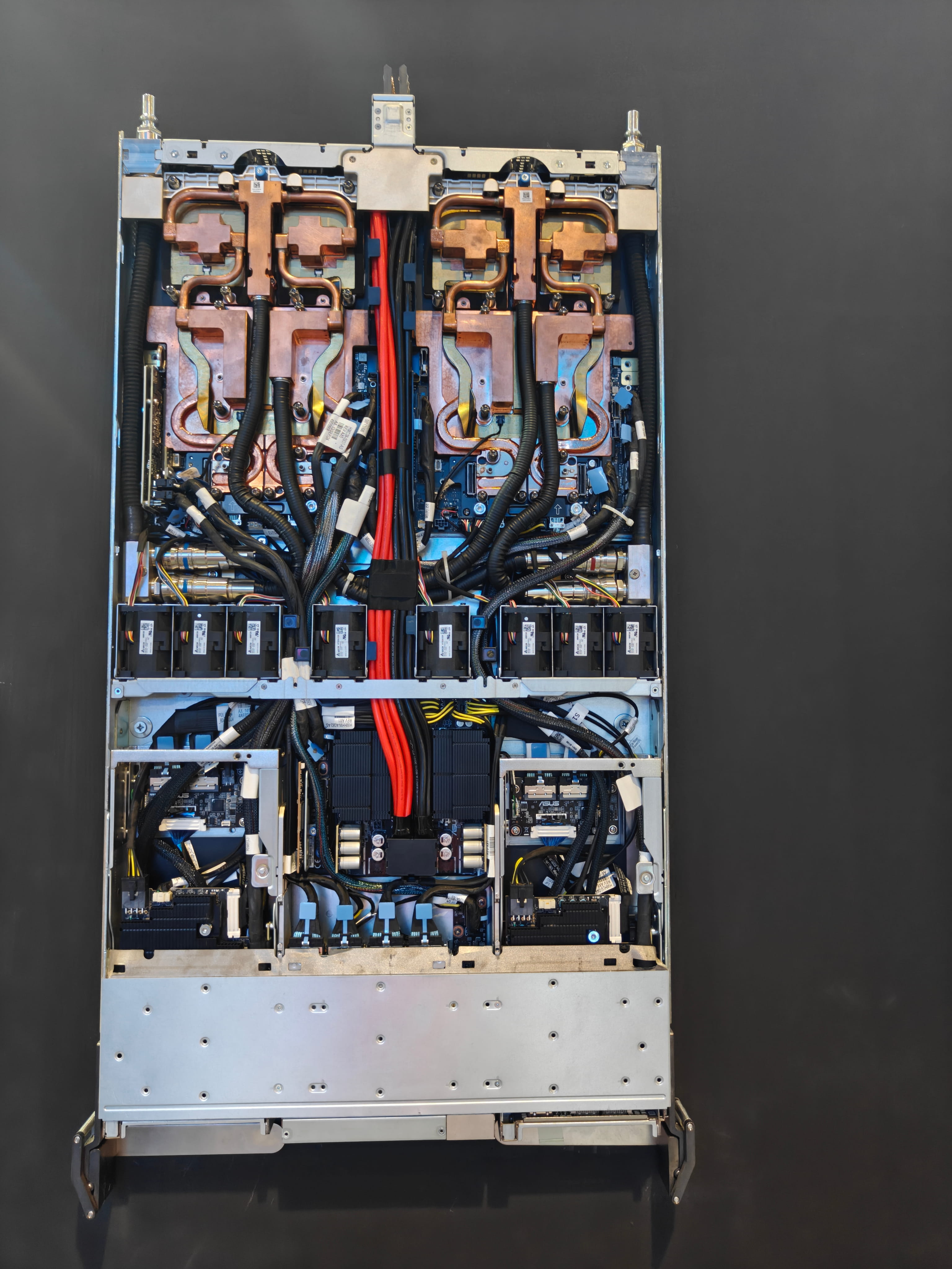
GPU performance depends on more than the accelerator itself. Compute, networking, memory, cooling, and topology need to be engineered as one system. Cyfuture AI's NVIDIA B300 GPU server infrastructure pairs each B300 GPU with 800 Gbps ConnectX-8 SuperNIC connectivity, NVSwitch 3.0 fabric, and direct liquid cooling.
The Difference Between GPU Fabric and Network Fabric
It's worth separating two communication layers that are easy to conflate. Inside the server, GPU-to-GPU communication runs over NVLink and NVSwitch — a purpose-built, high-bandwidth accelerator interconnect. Between servers, communication runs over the network fabric — NICs, InfiniBand or Ethernet/RoCE, and switches. NVLink/NVSwitch solves intra-node bandwidth; the NIC-based fabric solves inter-node reach. A cluster can have an excellent intra-node interconnect and still bottleneck badly at the inter-node layer if GPU-to-NIC connectivity and fabric design aren't engineered with equal care — which is exactly why this article treats them as separate but connected problems rather than one undifferentiated "networking" topic.
Network Oversubscription and Failure Domains
Oversubscription describes a ratio: if eight downlinks at, say, 400 Gb/s each (3.2 Tb/s aggregate) feed a leaf switch with only 1.6 Tb/s of uplink capacity toward the spine, that layer runs at 2:1 oversubscription. This example is illustrative, not a fixed industry number — real designs range from fully non-blocking to intentionally oversubscribed where traffic patterns and budget make that an acceptable trade-off. The impact of a given oversubscription ratio depends on how much traffic actually needs to cross that specific uplink, how bursty the collective communication pattern is, and how well the switch buffers and manages congestion when multiple flows compete.
Failure domains deserve equal attention. NIC failures, switch failures, and link failures are all more consequential in tightly coupled distributed training than in loosely coupled applications, because a single failed rank can stall an entire synchronous job. Whether 1:1 GPU-to-NIC connectivity increases or reduces failure-domain complexity depends on the design: dedicated NICs mean a single NIC failure affects one GPU's connectivity rather than several, which can be a resilience advantage — but it also means the cluster needs enough redundant paths and spare capacity to avoid that one GPU becoming a straggler that the whole job waits on.
B300 Networking vs B200 Networking
The B300 (Blackwell Ultra) and B200 share the same dual-reticle Blackwell die design, 208 billion transistors, and 160 SMs. The primary architectural change in B300 is memory: 288 GB of 12-high HBM3e versus the B200's 192 GB of 8-high HBM3e, at the same 8 TB/s bandwidth. NVLink 5 bandwidth (1.8 TB/s bidirectional per GPU) is consistent across the generation. The practical networking implication of the B300's larger memory is not a different NIC architecture by default — it's that workloads exploiting the extra memory (longer context windows, larger MoE expert counts, bigger per-GPU KV caches) generate larger collective-communication payloads, which raises the bar for what "sufficient" NIC bandwidth and non-blocking fabric design actually mean for that workload. Where a specific claim depends on a particular OEM's reference architecture rather than the B300 GPU generally — such as Cyfuture AI's own choice of 800 Gbps ConnectX-8 SuperNICs and NVSwitch 3.0 for its B300 GPU Server platform — that should be read as a platform-specific implementation, not a universal B300 specification.
Design Principles for a B300 GPU Cluster
1. Map Topology Deliberately
Decide GPU-to-NIC pairing at design time based on workload communication intensity, not as a default the server vendor happened to ship.
2. Preserve GPU-to-NIC Locality
Keep GPU and NIC on the same PCIe root/NUMA node wherever possible, and verify it with topology tools rather than assuming the wiring diagram matches reality.
3. Avoid Unnecessary Oversubscription
Size uplinks against the actual east-west traffic the workload generates, not against a generic ratio borrowed from enterprise networking.
4. Size the Fabric Around Collectives
Model expected AllReduce/AllGather traffic volume for your model size and GPU count before finalizing switch and uplink specifications.
5. Separate Local and External Fabrics
Treat NVLink/NVSwitch and the NIC-based network fabric as two distinct engineering problems with different bandwidth and latency profiles.
6. Measure Application-Level Scaling
Track step time and scaling efficiency directly, not just raw NIC or switch throughput numbers, since the application is the real measure of success.
7. Design for Failure and Maintenance
Plan redundant paths and spare capacity so a single NIC, link, or switch failure doesn't stall an entire synchronous job.
8. Expose Topology to Orchestration
Make GPU-NIC-switch topology visible to the scheduler so workload placement can respect locality instead of scattering ranks arbitrarily across racks.
Questions to Ask Before Buying or Renting a B300 Cluster
nvidia-smi topo -m show for GPU-to-NIC distance on the actual nodes?Your GPU Cluster Is Only as Fast as Its Data Path
High-performance AI infrastructure requires careful alignment between accelerators, NICs, switches, and workload communication patterns. Cyfuture AI's GPU-as-a-Service platform is built around exactly this end-to-end design discipline.
Designing the Network Layer of an AI Factory?
AI factories need compute, networking, storage, power, cooling, and orchestration designed as one production system, not procured piecemeal.

Planning a B300 GPU Deployment?
The right architecture starts with the entire data path — from GPU and NIC affinity to switching, storage, cooling, and workload orchestration. Cyfuture AI's NVIDIA B300 GPU server infrastructure is engineered as one system rather than a stack of separately sourced components.
Frequently Asked Questions
NVIDIA B300 network design refers to how GPUs, NICs, PCIe topology, and switch fabric are engineered together so that B300 accelerators — with up to 288 GB HBM3e and 1.8 TB/s NVLink 5 bandwidth per GPU — can communicate across nodes without the network limiting distributed training or inference performance.
It means each GPU is paired with its own dedicated NIC or NIC port rather than sharing an adapter with other GPUs, giving predictable, non-contended access to network bandwidth. It does not by itself guarantee a non-blocking fabric end to end.
A GPU can technically have an available NIC while still getting a worse data path because the NIC sits on a different PCIe root complex or NUMA node. Affinity ensures the GPU and its NIC share the same local PCIe hierarchy, minimizing latency and maximizing achievable bandwidth.
Not as a universal rule. 1:1 GPU-to-NIC is an architectural strategy that helps deliver predictable bandwidth and locality for bandwidth-intensive workloads. Whether it's necessary depends on workload communication pattern, NIC speed, PCIe topology, and fabric capacity.
Remote Direct Memory Access lets a network adapter read or write memory on a remote system with reduced CPU involvement, lowering latency and CPU overhead for high-frequency, high-volume data transfers such as collective communication in distributed AI training.
GPUDirect RDMA lets a compatible NIC transfer data directly to and from GPU memory, bypassing a copy through host system memory. It requires matching hardware, driver, and network-stack support — it is not automatically present in every B300 deployment.
InfiniBand offers native RDMA and hardware-level congestion control on a purpose-built HPC/AI fabric. RoCE carries RDMA over Ethernet and can match InfiniBand's benefits with proper lossless-fabric configuration or a purpose-built stack such as NVIDIA Spectrum-X. Neither is universally superior; the right choice depends on scale and operational fit.
A network is non-blocking at a given layer when aggregate downstream bandwidth does not exceed available upstream bandwidth at that layer, for the traffic pattern in question. It should be assessed against actual port speeds, uplink counts, and switch topology — not assumed from a leaf-spine diagram alone.
Oversubscription is the ratio between downstream demand and available uplink capacity at a network layer — for example, 8 GPUs' worth of downlink bandwidth feeding into half that capacity of uplink bandwidth is 2:1 oversubscription. Its real-world impact depends on actual traffic patterns and congestion behavior.
When the network can't keep pace with collective-communication demand, GPUs wait for synchronization to complete before starting the next compute step. That wait time lowers effective GPU utilization even though the GPU's raw compute capability is unchanged, which lengthens training runtime and raises cost per useful compute.
Data, tensor, and pipeline parallelism all require frequent GPU-to-GPU synchronization — gradient all-reduce, activation exchange, and pipeline hand-offs — that flows directly between accelerators and nodes rather than through a traditional client-server path, producing heavy east-west traffic.
B300 and B200 share the same dual-reticle Blackwell die design, transistor count, and NVLink 5 bandwidth per GPU. The B300's main change is memory — 288 GB versus 192 GB of HBM3e — which increases the size of collective-communication payloads for memory-bound workloads, raising the bar for adequate NIC and fabric bandwidth rather than requiring a fundamentally different network architecture.
Cyfuture AI's NVIDIA B300 GPU Server infrastructure is built with 800 Gbps ConnectX-8 SuperNIC networking and NVSwitch 3.0 fabric, alongside direct liquid cooling and Gen5 NVMe storage, deployed from India-hosted, DPDP Act-compliant data centers.
Ask about the GPU-to-NIC ratio and whether bandwidth is dedicated or shared, which NIC technology and RDMA/GPUDirect RDMA support is in place, the fabric type (InfiniBand or RoCE Ethernet), leaf and spine oversubscription ratios, PCIe/NUMA locality, failure redundancy, and whether network telemetry is correlated with application-level performance.
No. It is one architectural strategy that helps provide predictable bandwidth and locality for bandwidth-intensive, tightly synchronized workloads. Lighter or less synchronization-sensitive workloads may perform acceptably with shared NIC resources; the right ratio depends on the workload, NIC capability, and fabric design as a whole.