


 IND
IND UAE
UAE SA
SA



The Thermal Problem Behind AI Infrastructure
Power density tells the story. A high-performance GPU accelerator designed for AI training can draw several hundred watts — sometimes more — from a single slot in a server. Pack eight of those into a 4U chassis, add NVLink interconnects, high-speed NICs, and NVMe storage, and you have a server consuming several kilowatts. Now fill a rack with those servers.
Traditional data center cooling was designed for rack densities that look nothing like this. Raised-floor computer rooms moving chilled air through perforated tiles work well when racks pull 5–10 kW. They struggle, and sometimes fail outright, when a liquid-cooled data center alternative is warranted at densities three to five times that. The physics haven't changed — moving enough conditioned air to manage that thermal load requires enormous airflow volumes, precision containment, and space that most facilities weren't designed to accommodate.
This is the engineering reality behind a shift that's been happening in large-scale AI infrastructure for several years. The question isn't whether liquid cooling is a better technology in the abstract. It's whether a given rack's thermal load can be managed with air alone, and at what cost. For a growing portion of GPU clusters, the answer points toward liquid.
What Is a Liquid-Cooled Data Center?
A liquid-cooled data center is a facility that uses liquid — typically water, a water-glycol mixture, or in some cases a dielectric fluid — as part of the thermal management path for IT equipment. That's the precise definition, and it's worth holding onto because the term gets used loosely.
Liquid cooling does not mean every server is submerged in fluid. It does not mean the air conditioning is gone. Most production liquid-cooled data centers use a hybrid approach: liquid handles the high-density compute nodes where heat concentration is greatest, while air cooling continues to serve storage, networking, and lower-density compute.
Three distinct approaches fall under the "liquid cooling" umbrella:
Direct-to-Chip Cooling
Cold plates mount directly on GPU and CPU dies. Coolant circulates through machined channels in the cold plate, absorbing heat at the chip surface. The server chassis remains largely conventional. Most enterprise AI GPU infrastructure uses this approach.
Immersion Cooling
Entire servers or compute boards are submerged in a tank of dielectric fluid. The fluid contacts all components simultaneously, removing heat across the full hardware surface. Requires purpose-built hardware, tanks, and fluid management. Higher heat removal potential but more complex to deploy and maintain.
Rear-Door Heat Exchangers
A liquid-cooled panel replaces the rear door of a standard server rack. Air from the servers passes through this panel, where heat transfers into a water loop. The air leaving the rack is cooled before entering the room. A useful intermediate approach that doesn't require server modification.
Why AI Workloads Changed the Cooling Equation
Traditional enterprise servers — running databases, web applications, ERP systems — have a characteristic thermal profile. Compute is distributed across many moderately dense racks. Utilisation cycles up and down. Cooling systems designed for average load with headroom for peaks work adequately.
AI workloads have a different profile entirely. GPU training runs operate at sustained high utilisation — a well-configured training job keeps the GPUs near full load continuously for hours, days, or weeks. That's the point. The economics of GPU compute make continuous utilisation the goal, not an exception.
The hardware reflects this. Multi-GPU servers like NVIDIA's HGX platform stack high-end GPUs with tightly coupled NVLink interconnects in dense configurations. The thermal output of a fully populated HGX server is concentrated in a small physical footprint. Inference servers optimised for throughput show similar patterns — multiple GPUs, sustained load, compact chassis.
A rack populated with standard 1U dual-socket servers might draw 10–15 kW under load. A rack of high-density AI GPU servers can reach 50–100 kW or beyond depending on the hardware generation and configuration. Cooling systems designed for the former simply don't have the capacity for the latter — it's a physical constraint, not a configuration problem.
High-performance networking compounds the issue. InfiniBand and high-speed Ethernet switches connecting GPU clusters run hot, and the fiber and cable density in AI data center aisles can obstruct the airflow patterns that traditional cooling relies on. Liquid-cooled AI data center designs address this by moving thermal management out of the airstream entirely for the components that produce the most heat.
How Liquid-Cooled Data Centers Work
The thermal path in a liquid-cooled system is sequential. Heat generated at the chip surface moves through a series of interfaces and components before being rejected to the environment. Understanding each step makes it clear why this architecture handles high-density loads differently from forced-air systems.
Heat Is Generated at the GPU Die
GPU transistors switching at high frequency dissipate power as heat. In a high-performance GPU, billions of transistors operate simultaneously during compute workloads — the thermal output is concentrated in an area of just a few hundred square millimetres. The junction temperature of the die must remain within operating limits for the GPU to sustain performance. This is where the thermal challenge originates.
Heat Conducts Into the Cold Plate
A cold plate — a precision-machined block, typically copper or aluminium — sits on top of the GPU die with a thin layer of thermal interface material (TIM) between them. TIM fills microscopic air gaps in the metal surfaces that would otherwise impede heat transfer. Heat conducts from the die through the TIM into the cold plate body. The cold plate's internal structure — a network of channels or microchannels — is designed to maximise the surface area available for heat exchange with the coolant.
Coolant Absorbs Heat as It Flows Through the Cold Plate
Coolant — typically deionised water, a water-glycol mixture, or a purpose-formulated fluid — flows through the channels in the cold plate under pressure from pumps in the Cooling Distribution Unit. The coolant enters cooler than the cold plate and absorbs heat as it passes through. Water's specific heat capacity is approximately 4,186 J/(kg·K), which is why water-based coolants can carry much more thermal energy per unit volume than air at the same flow rate. The coolant exits the cold plate warmer, carrying the GPU's heat with it.
Heated Coolant Travels to the CDU via Manifolds
Flexible tubing connects each cold plate to a rack-level manifold — a distribution header that consolidates coolant from multiple cold plates in the server. From the server manifold, coolant travels through quick-disconnect fittings to the rack manifold, and from there to the Cooling Distribution Unit (CDU). The tubing and fittings are designed for serviceability: quick disconnects allow servers to be removed without draining the entire system.
The CDU Transfers Heat to the Facility Water Loop
Inside the CDU, a heat exchanger separates the IT cooling loop (the fluid that touches server components) from the facility water loop. Heat passes across the heat exchanger from the warmer IT loop to the cooler facility water loop. This separation is important: facility water, which may be harder or contain traces of biological growth inhibitors, never contacts the sensitive IT equipment. The IT loop uses controlled, filtered fluid. The facility water loop connects to the building's chilled water or condenser water infrastructure.
Heat Is Rejected to the Environment
The facility water loop carries heat away from the CDU to one of several rejection systems: a chiller that uses refrigeration to cool the water, a cooling tower that rejects heat through evaporation, or a dry cooler/fluid cooler that uses ambient air when conditions permit. In some implementations, the heat can be recovered for building heating or other uses. The specific rejection method depends on the facility design, climate, and efficiency targets.
Cooled Fluid Returns to the IT Equipment
The CDU's pumps push cooled fluid back through the supply manifolds to the cold plates, completing the loop. The CDU continuously monitors and adjusts coolant temperature, pressure, and flow rate based on sensor inputs. This closed-loop process runs continuously during server operation, maintaining chip temperatures within safe operating bounds regardless of how long the workload runs.
Liquid Cooling Architecture: Three Layers
A production liquid-cooled data center has three distinct architectural layers, each with its own components and engineering requirements. They need to be designed as a system — mismatches between layers are a common source of problems in deployments that were planned piecemeal.
IT Equipment Layer
This is where heat originates and where liquid cooling interfaces with the server hardware. Components at this layer include: GPU and CPU cold plates, thermal interface materials, server-internal tubing, server manifolds, and quick-disconnect fittings at the chassis boundary. Server design matters here — not all servers are designed for direct liquid cooling, and retrofitting air-cooled servers is rarely practical at scale.
Facility / Cooling Infrastructure Layer
The CDU sits here, along with rack manifolds, supply and return headers running through the data center, pumps, sensors, control systems, and leak detection infrastructure. This layer bridges the IT equipment and the building's utility systems. The CDU is the most important component at this layer — its capacity, control quality, and redundancy configuration determine the cooling system's overall reliability.
Heat Rejection Layer
The building systems that ultimately remove heat from the facility. This includes chillers, cooling towers, dry coolers, condenser water systems, and the mechanical plant. For AI data centers in India, the heat rejection design needs to account for high ambient temperatures and monsoon humidity — factors that affect the efficiency of different rejection technologies differently.
A common planning mistake: specifying the CDU based on server thermal load but not matching the facility water loop capacity, or designing the heat rejection layer for a lower density than the IT layer will eventually need. All three layers must be sized and designed as a coherent system. Upgrading one layer while the others remain constrained produces a bottleneck that can't be resolved without a larger redesign.
Key Components Explained
Cold Plates
Cold plates are precision-machined metal blocks — copper is the most common material for its thermal conductivity — that mount directly on GPU and CPU dies. Internally, they contain a network of channels through which coolant flows. The channel geometry is engineered to maximise heat transfer: tighter, more numerous channels increase surface area but also increase flow resistance, requiring more pump pressure. High-performance cold plates designed for AI GPUs can transfer hundreds of watts per plate with coolant temperature rises of a few degrees Celsius across the plate. The interface between cold plate and die is bridged by thermal interface material — a compound that fills surface irregularities and ensures consistent, low-resistance thermal contact.
Coolant
The fluid choice affects heat transfer efficiency, corrosion characteristics, freeze protection, biological growth risk, and compatibility with system materials. Deionised water has excellent thermal properties but limited corrosion inhibition and can support biological growth if not treated. Water-glycol mixtures add freeze protection and corrosion inhibitors. Some deployments use purpose-formulated heat transfer fluids that combine good thermal performance with built-in corrosion and biocide packages. The fluid must be compatible with all wetted materials in the system — copper, aluminium, elastomer seals, stainless steel — because incompatible combinations cause corrosion and material degradation over time.
Pumps
CDU-integrated pumps circulate coolant at controlled pressure and flow rate. Pump sizing must account for the pressure drop across all cold plates, tubing, manifolds, and heat exchanger elements in the system — undersized pumps produce insufficient flow and degrade cooling performance. Redundant pump configurations (N+1 at minimum) are standard practice in production deployments because pump failure while servers are under load can cause thermal shutdown. Variable-speed pump drives improve efficiency by matching flow to actual thermal load rather than running at maximum continuously.
Manifolds and Distribution Headers
Manifolds distribute coolant from a single supply line to multiple cold plates within a server or from a rack header to multiple servers. They consolidate return coolant for transport to the CDU. Well-designed manifolds ensure balanced flow across all branches — if one branch receives significantly more or less flow than others, temperatures across the GPU cluster become uneven. Rack-level manifolds connect to facility-level supply and return headers, which run through the data center floor or overhead to connect multiple CDUs to the facility water plant.
Quick Disconnects
Quick disconnects are the fittings that allow individual servers or components to be removed from the liquid cooling system for maintenance without draining the entire rack. A dry-break quick disconnect closes both halves when separated, preventing fluid loss and air ingestion. The quality of these fittings matters operationally — leaking or unreliable disconnects create service events and potential fluid ingress into server hardware. In high-density AI racks, where maintenance access must be fast and clean, quick disconnect reliability is a meaningful design factor.
Sensors and Control Systems
A production liquid cooling system requires continuous monitoring of coolant supply and return temperatures at multiple points, system pressure (to detect leaks or pump issues), flow rate, and leak detection from sensors placed at low points in the system where fluid would pool if a leak occurred. CDUs typically include an integrated controller that maintains coolant temperature setpoints by adjusting pump speed and, in some designs, controlling a mixing valve that blends supply and return fluid. This telemetry should feed into the data center's broader monitoring infrastructure so cooling anomalies trigger alerts before they cause hardware protection events.
The Cooling Distribution Unit (CDU)
The CDU deserves its own explanation. It's the component that makes rack-level liquid cooling a manageable system rather than a complex plumbing project.
At its core, a CDU contains three main systems: a pump set that circulates coolant to IT equipment, a heat exchanger that transfers heat between the IT cooling loop and the facility water loop, and a control system that manages both. The pump set maintains the pressure differential that drives coolant through the cold plates and back. The heat exchanger keeps the two water loops thermally coupled but physically separated.
The loop separation the CDU provides is operationally significant. Facility water systems are typically treated with biocides and may have varying hardness depending on local water supply. Introducing facility water directly into server cold plates would deposit minerals and potentially cause corrosion damage over time. The CDU's heat exchanger allows the IT loop to use controlled, filtered fluid while the facility water system handles the bulk of heat transport to the mechanical plant.
CDU capacity is specified in kW of heat transfer — a CDU serving a row of high-density AI racks needs to be sized for the maximum thermal load across all connected servers, not average load. Redundancy configuration (N, N+1, or 2N depending on criticality) follows the same principles as power redundancy in data center design.
Direct-to-Chip Liquid Cooling Explained
Direct-to-chip cooling is the approach most commonly deployed in AI GPU infrastructure today. It's worth understanding precisely because the name can be misleading — coolant does not contact the chip directly.
What happens is this: a cold plate is mechanically clamped to the GPU die with thermal interface material filling the interface. The cold plate is a sealed metal assembly; coolant flows through its internal channels but is completely enclosed. Heat from the GPU surface conducts through the TIM and into the cold plate metal, then transfers to the coolant through convection across the channel walls. The chip sees the cold plate as a large, very effective heat sink. The coolant sees the cold plate as a warm wall to absorb heat from.
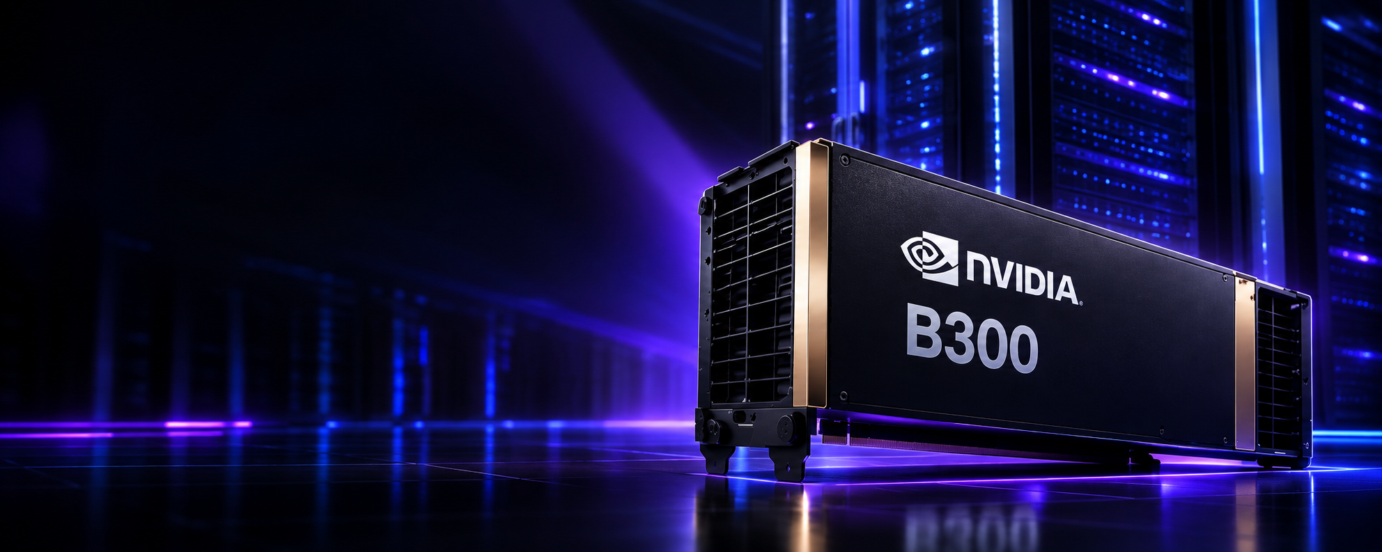
Direct-to-chip cooling can be implemented with server hardware that is largely compatible with standard data center racks and power infrastructure. The cooling loop adds plumbing but doesn't require the server to be redesigned from scratch. For enterprises deploying GPU servers such as the NVIDIA B200 or NVIDIA B300, direct-to-chip variants of these platforms are available from server OEMs and can be integrated into racks with CDU-based cooling infrastructure.
A server configured for direct-to-chip cooling replaces the heatsink/fan assembly on each GPU and CPU with a cold plate. Internal tubing connects the cold plates to a server manifold with quick-disconnect fittings at the rear of the chassis. When the server is inserted into a rack, the quick disconnects engage with rack manifold ports, connecting the server to the coolant supply and return. The design allows hot-swap removal of servers without draining the rack's coolant loop.
Residual heat from components not covered by cold plates — memory, VRMs, storage — is still handled by airflow, either from fans within the chassis or from supplemental rack-level airflow. Most direct-to-chip implementations are hybrid: liquid handles 60–80% of the server's thermal load at the GPU and CPU, while air handles the remainder.
Direct-to-Chip vs Immersion Cooling
| Feature | Direct-to-Chip Cooling | Immersion Cooling |
|---|---|---|
| Cooling Method | Cold plates on GPU/CPU dies; coolant flows through enclosed channels | Entire server or compute board submerged in dielectric fluid tank |
| GPU Contact | Cold plate contacts GPU via TIM — coolant is enclosed, never contacts die | Dielectric fluid contacts all surfaces including PCB and components directly |
| Server Modification | Cold plates replace heatsinks; server chassis remains largely standard | Servers typically require significant modification — fans removed, components must be compatible with fluid |
| Infrastructure | CDU, rack manifolds, supply/return headers — fits standard rack form factor | Specialised immersion tanks, fluid management systems, modified rack infrastructure |
| Heat Transfer Coverage | Covers GPU/CPU; residual component heat handled by supplemental airflow | Covers all components simultaneously — potentially higher total heat capture |
| Maintenance | Quick disconnects allow server removal with minimal disruption; familiar procedures | Removing servers requires extracting from fluid, cleaning before work — more involved procedures |
| Typical Applications | Enterprise AI data centers, GPU cloud, HPC facilities — mainstream adoption | Specialised HPC, cryptocurrency, research environments — currently less mainstream |
| Deployment Considerations | Compatible with more standard server hardware; lower barrier to adoption | Higher upfront infrastructure cost; requires careful fluid selection and management; growing ecosystem |
Neither approach is universally superior. Immersion has higher theoretical heat capture potential — submerging the entire board removes heat from components that direct-to-chip cold plates don't reach. Direct-to-chip is currently more practical for organisations deploying standard GPU server platforms and integrating with existing rack infrastructure. For most enterprise AI deployments today, direct-to-chip is the mainstream choice while immersion cooling sees growing adoption in more specialised high-performance computing contexts.
Liquid Cooling vs Air Cooling
| Characteristic | Liquid Cooling | Air Cooling |
|---|---|---|
| Heat Transfer Medium | Water or water-glycol — specific heat ~4,186 J/(kg·K) | Air — specific heat ~1,005 J/(kg·K) |
| High-Density GPU Support | Well-suited for dense AI GPU configurations; handles concentrated loads | Effective within certain density limits; challenges increase significantly at very high rack kW |
| Rack Density | Enables higher rack densities when designed correctly | Practical upper limit depends on facility design; typically lower than liquid-cooled equivalents |
| Infrastructure Complexity | Plumbing, CDUs, leak detection, fluid management required | CRAC/CRAH units, containment, airflow management — familiar and well-understood |
| Server Compatibility | Requires liquid-cooling-compatible server hardware | Works with any standard server; no hardware modification needed |
| Noise | Lower server fan noise; CDU pumps are quieter than high-speed server fans | High-speed server fans at full load are significant noise sources |
| Maintenance Familiarity | Requires fluid system expertise; procedures differ from air-cooled environments | Well-understood by most data center operations teams |
| Can They Coexist? | Yes — most AI data centers use liquid cooling for GPU nodes and air cooling for networking and lower-density compute | |
Air cooling isn't obsolete. For workloads running on standard compute at moderate rack densities, it remains a practical and well-understood approach. The shift toward liquid cooling is driven by specific requirements — concentrated heat loads from high-performance GPUs — not by a general consensus that air cooling is inadequate. Many data centers operate mixed environments, with liquid cooling serving GPU clusters while air handles everything else.
Why GPUs Need Liquid Cooling
High-performance GPUs designed for AI workloads are thermally demanding in two compounding ways: high absolute power draw and high power density. A modern GPU for AI can consume well over 300 watts — some are rated significantly higher. That power is concentrated in a die area measured in square centimetres. The resulting heat flux — watts per unit area — is very high, and removing it efficiently requires an effective thermal path from die to environment.
In air-cooled configurations, heat moves from the die through a heatsink into the air, which fans then move out of the chassis. This works but has limits. The thermal resistance from die to air is higher than die to liquid, meaning the chip must run hotter relative to ambient to drive the same heat flow. At high power levels, this can push junction temperatures closer to operational limits, which may trigger thermal throttling — the GPU reducing its clock speed to manage heat.
NVIDIA H100 & H200
Available in SXM5 form factor with high-bandwidth memory, these GPUs are designed for dense multi-GPU configurations. Both air-cooled and liquid-cooled server platforms exist. High-density deployments with multiple GPUs per server typically use liquid-cooled variants to manage thermal load sustainably at scale.
NVIDIA B200 & B300
Blackwell-generation GPUs with higher compute density than Hopper. Multi-GPU server configurations built around these chips are available in liquid-cooled variants. As GPU TDPs increase with each generation, liquid cooling becomes more relevant to maintaining sustained performance in production AI environments.
The Trend Line
Each GPU generation has generally increased in TDP relative to its predecessor. The hardware roadmaps from GPU manufacturers point toward continued increases in per-GPU compute density, which tends to correlate with thermal output. Infrastructure designed for today's generation should be planned with this trajectory in mind.
No. Whether a specific GPU deployment requires liquid cooling depends on the server configuration, rack density, thermal load, and facility design. Single-GPU or dual-GPU servers at moderate rack densities can often be managed with air cooling. It's when density increases — 4-GPU, 8-GPU configurations in dense racks — that liquid cooling becomes practically relevant. Always verify requirements against the server OEM's thermal specifications for the specific configuration you're deploying.
Rent NVIDIA GB200 NVL — Blackwell at Scale
The GB200 NVL pairs two B200 GPUs and one Grace CPU on a single NVLink domain, delivering exceptional performance for large-scale AI training and inference. Available on Cyfuture AI's liquid-cooled infrastructure with India-hosted data sovereignty and INR billing.
Benefits of Liquid-Cooled Data Centers
Higher Achievable Rack Density
Liquid cooling removes the thermal ceiling that air cooling imposes on rack power. Racks that would require significant airflow infrastructure — containment, raised floor, dedicated CRAH units — at high kW levels can be cooled more compactly when liquid handles the thermal load. This enables more compute per floor tile, which matters when data center space is expensive or constrained.
More Efficient Heat Removal at Source
Liquid's thermal capacity allows heat removal at lower temperature differentials. Cold plates can maintain GPU junction temperatures well within safe operating range even under sustained full load, without the thermal resistance penalty that air-cooled heatsinks carry. More stable operating temperatures mean consistent GPU performance and potentially extended hardware longevity.
Reduced Airflow Requirements
When liquid handles 60–80% of server thermal load, the remaining components produce less heat for air to manage. Server fan speeds can be lower, reducing both noise and fan power consumption. The room-level airflow infrastructure — CRAC units, containment, raised floor plenum — can be right-sized for a lower residual heat load rather than the full server output.
Support for GPU-Intensive AI Workloads
AI training and inference at scale involve sustained GPU utilisation. Liquid cooling makes high sustained load thermally manageable, enabling GPUs to run at rated TDP for extended periods without throttling. For GPU cloud services where customers pay for compute performance, consistent GPU throughput depends on consistent thermal management.
Future Scalability
Data centers with liquid-ready infrastructure — CDU capacity, supply/return headers, adequate facility water plant — can accommodate future GPU generations without facility redesign. As GPU TDPs increase across hardware generations, the cooling infrastructure already in place can serve the new hardware, sometimes with CDU upgrades rather than complete infrastructure replacement.
Potential for Heat Recovery
Liquid cooling produces a concentrated stream of warm water rather than warm air diffused throughout the facility. Depending on facility design and return fluid temperature, this thermal output can potentially be recovered for building heating or other applications. This is more relevant in some climates and facility types than others, but the architectural possibility doesn't exist with air-cooled systems.
Are Liquid-Cooled Data Centers More Energy Efficient?
The short answer: it depends on the complete facility design, not just the cooling technology in the server rack.
Liquid cooling can reduce the energy consumed by server-level fans significantly, because less airflow is needed when liquid handles most of the thermal load. At the facility level, liquid cooling enables higher-temperature chilled water in some designs — warm-water cooling systems that supply fluid at 35–45°C can use more efficient chillers or operate in free-cooling mode more frequently in temperate climates.
But liquid cooling also adds pump energy, and in some implementations requires chillers to maintain precise fluid temperatures that air-cooled facilities don't need. A poorly designed liquid-cooled facility can have worse PUE than a well-designed air-cooled one. The technology is a tool — efficiency outcomes depend on how that tool is integrated into the total facility design.
Vendors sometimes imply that liquid cooling achieves a specific PUE. Be sceptical of precise figures without facility context. PUE is determined by the complete infrastructure — power distribution losses, cooling plant efficiency, IT load factor, and climate. The same liquid cooling technology in two different facilities will produce different PUE values. What liquid cooling can do is reduce the cooling overhead on a per-kW-IT basis when designed well into a complete system.
Liquid Cooling and the AI Infrastructure Stack
Cooling isn't isolated from the rest of the AI infrastructure stack — it's a dependency that must be sized and designed alongside compute, networking, storage, and power. Getting the GPU selection right while underspecifying the cooling system produces a constrained deployment where the hardware can't sustain its rated performance.
Each layer of this stack has dependencies on the others. CDU capacity must be sized to the maximum GPU thermal load, not average utilisation — training workloads can sustain near-peak GPU power for extended periods. Power infrastructure must account for pump and control loads on top of IT power. And the facility water plant must be able to reject heat at the rate the CDUs demand even during peak AI workload periods, which may coincide with hot weather that reduces cooling tower efficiency.
Build AI Infrastructure Without the Cooling Complexity
Planning high-density AI workloads? Cyfuture AI's liquid-cooled infrastructure is designed for demanding GPU workloads — from NVIDIA B200 training clusters to high-throughput inference deployments. India-hosted, DPDP compliant, ISO 27001:2022 certified.
Challenges and Planning Considerations
Liquid-cooled data centers are not a plug-and-play upgrade. The technical and operational considerations are significant enough that organisations that underestimate them tend to have difficult deployments.
Infrastructure & Capital Challenges
- Higher upfront cost — CDUs, manifolds, leak detection, and facility water modifications add capital cost beyond what an equivalent air-cooled deployment requires
- Plumbing infrastructure — supply and return headers, connections to facility water plant, pressure testing, and commissioning add project complexity
- Server hardware compatibility — not all servers support liquid cooling; liquid-cooled variants cost more than air-cooled equivalents
- Retrofitting is complex — existing air-cooled data centers designed around raised-floor airflow need significant modification
- Facility water requirements — adequate facility water capacity and quality must be available or built
Operational Challenges
- Leak risk — any water-based system carries leak risk; detection, containment, and response procedures must be planned and rehearsed
- Fluid management — coolant must be tested, treated, and maintained; quality degradation causes corrosion and biofilm formation
- Staff training — operations teams trained on air-cooled data centers need additional skills for fluid systems
- Maintenance procedures — different from air-cooled environments; quick disconnect procedures, leak response, and filter replacement schedules need documentation
- Vendor ecosystem — fewer service providers are experienced with liquid cooling compared to air cooling
For organisations that want the performance benefits of liquid-cooled GPU infrastructure without building and operating the cooling systems themselves, managed GPU cloud services on liquid-cooled infrastructure are an alternative. Cyfuture AI's GPU as a Service platform provides access to liquid-cooled GPU compute without requiring customers to manage the underlying cooling infrastructure.
Designing a Liquid-Cooled AI Data Center
For organisations designing their own liquid-cooled infrastructure, the following checklist covers the major decision points. Each item has downstream dependencies — working through them in order avoids costly late-stage redesigns.
- Define GPU hardware selection (H100, H200, B200, B300) and confirm liquid-cooled server variants
- Calculate total rack thermal load at maximum GPU TDP — not average utilisation
- Specify CDU cooling capacity with N+1 or 2N redundancy
- Design rack manifold configuration for the selected server hardware
- Plan facility supply and return header routing through the data center
- Confirm facility water loop capacity and quality requirements
- Select heat rejection method (chiller, cooling tower, dry cooler) appropriate to climate
- Size mechanical plant for full liquid cooling load plus residual air cooling load
- Specify coolant fluid and compatible materials for all wetted components
- Design leak detection sensor placement at CDU, rack manifolds, and low-floor points
- Plan monitoring integration — CDU telemetry to data center management system
- Size power infrastructure for IT load plus cooling auxiliary power (pumps, controls)
- Design high-speed networking interconnect layout accounting for cable density
- Plan parallel file system or storage infrastructure for AI training data throughput
- Document maintenance procedures and staff training requirements before go-live
- Plan for future expansion — CDU capacity headroom, header capacity, power headroom
Rent NVIDIA B300 GPU — Next-Generation AI Compute
The NVIDIA B300 delivers higher compute throughput than the B200 with increased HBM3e memory capacity, making it the GPU of choice for the most demanding LLM training and inference workloads. Deploy on Cyfuture AI's liquid-cooled infrastructure with full India data residency.
Blackwell and Next-Generation GPU Cooling
NVIDIA's Blackwell architecture — the B200 and B300 GPUs — represents the current leading edge of GPU compute for AI. From a cooling perspective, these GPUs are available in both air-cooled and liquid-cooled server configurations, and the liquid-cooled variants are designed specifically for high-density multi-GPU deployments where rack power levels make air cooling impractical.
The NVIDIA B300 GPU server in liquid-cooled configuration represents the kind of deployment where cooling architecture is as important a design consideration as the GPU itself. Getting the CDU sizing, manifold design, and facility water capacity right is what enables the hardware to sustain its rated performance under production AI workloads.
The trajectory across GPU generations points in one direction: higher compute density in the same physical footprint, which correlates with higher thermal output per unit area. Infrastructure teams planning for 3–5 year deployment cycles should design cooling infrastructure with this trajectory in mind — oversizing cooling capacity relative to today's GPUs is often cheaper than retrofitting when the next generation of hardware arrives.
NVIDIA's GB300 NVL72 and similar rack-scale AI systems — where GPU and NVLink interconnect infrastructure are integrated at the rack level — are designed around liquid cooling from the start. These systems deliver compute density that isn't feasible without liquid thermal management. Infrastructure teams evaluating next-generation rack-scale AI systems should treat liquid cooling as a prerequisite, not an option, when specifying facilities.
Cyfuture AI's Liquid-Cooled AI Infrastructure
Cyfuture AI operates liquid-cooled AI data centers in India across three Tier III+ facilities in Noida, Jaipur, and Raipur. The infrastructure is designed for high-density GPU deployments supporting AI training, inference, and HPC workloads — use cases where sustained GPU performance depends on effective thermal management.
Key aspects of Cyfuture AI's liquid-cooled infrastructure relevant to enterprise AI buyers:
NVIDIA B200 & B300 GPU Support
Liquid-cooled infrastructure supporting current-generation Blackwell GPUs for large-scale AI training and inference deployments, with the thermal capacity to sustain these workloads at rated performance.
DPDP Act Compliance
All AI processing — including model training data and inference outputs — stays within Indian borders. ISO 27001:2022 and SOC 2 Type II certifications cover the complete infrastructure stack, including cooling and facility systems.
INR Billing, No FX Exposure
GPU cloud services and dedicated infrastructure contracts billed in INR with GST-compliant invoicing. Enterprise AI teams get predictable infrastructure costs without currency risk on multi-year deployments.
For organisations that don't want to build and operate their own liquid-cooled GPU infrastructure, Cyfuture AI offers GPU as a Service on liquid-cooled compute — access to high-density GPU capacity without the operational overhead of managing cooling systems, facility infrastructure, or hardware procurement.
Ready for High-Density AI Compute?
Explore Cyfuture AI's liquid-cooled infrastructure for GPU-intensive AI workloads — from NVIDIA B200 training clusters to large-scale inference. Discuss the right deployment model for your organisation's AI roadmap.
Frequently Asked Questions
A liquid-cooled data center is a facility that uses liquid — typically water, a water-glycol mixture, or a dielectric fluid — as part of the thermal management path for IT equipment. Rather than relying entirely on airflow, liquid cooling transfers heat from hot components (GPUs, CPUs) into a circulating fluid, which carries it to a heat rejection system. The term covers multiple approaches including direct-to-chip cooling, immersion cooling, and rear-door heat exchangers. Most production liquid-cooled data centers use a hybrid approach: liquid for high-density GPU nodes, air for networking and lower-density compute.
The thermal path has seven stages: (1) Heat is generated at the GPU die during computation. (2) Heat conducts through thermal interface material into a cold plate mounted on the chip. (3) Coolant flowing through channels in the cold plate absorbs the heat. (4) Heated coolant travels via manifolds and tubing to the Cooling Distribution Unit (CDU). (5) Inside the CDU, a heat exchanger transfers heat from the IT cooling loop to the facility water loop, keeping the two fluids separate. (6) The facility water loop carries heat to a chiller, cooling tower, or dry cooler where it is rejected to the environment. (7) Cooled fluid returns from the CDU through the supply manifolds to the cold plates, completing the closed loop.
Direct-to-chip cooling mounts cold plates on individual GPU and CPU dies. Coolant circulates through sealed channels inside the cold plate — it doesn't contact the chip or circuit board directly. The server chassis remains largely standard, and servers can be maintained using familiar procedures. Immersion cooling submerges entire servers in a tank of dielectric fluid that contacts all components simultaneously. Immersion has higher theoretical coverage but requires purpose-built tanks, modified hardware, and more complex fluid management. Direct-to-chip is more widely adopted for enterprise AI GPU infrastructure today. Immersion sees use in specialised HPC and research environments.
A CDU is the central device managing coolant flow in a rack or row liquid cooling system. It contains: pumps that circulate coolant to IT equipment; a heat exchanger that transfers heat from the IT cooling loop to the facility water loop while keeping the two fluids physically separate; sensors monitoring temperature, pressure, and flow; and controls that maintain coolant setpoints by adjusting pump speed and mixing. The CDU isolates sensitive IT cooling fluid from facility water, which may contain minerals or biocides incompatible with server components. CDU capacity is rated in kW of heat transfer and must be sized for peak thermal load, not average.
No. Liquid cooling is more effective for high-density GPU workloads where concentrated heat loads exceed what air cooling can practically manage. For workloads on standard compute at moderate rack densities, air cooling remains a practical and well-understood approach. The two are not mutually exclusive — most AI data centers use liquid cooling for GPU nodes and air cooling for networking, storage, and lower-density compute. Liquid cooling adds infrastructure complexity and upfront cost; it should be specified where the thermal requirements justify it, not universally.
AI training and inference workloads run dense GPU clusters at sustained high utilisation, producing concentrated heat loads that challenge traditional air cooling. High-performance GPU servers can drive rack power densities well above what forced air can manage economically. Liquid cooling removes heat directly at the chip surface, enabling higher rack densities, maintaining stable GPU temperatures under sustained load (which prevents thermal throttling), and reducing the volume of conditioned airflow required. As GPU TDPs have increased across generations, liquid cooling has become increasingly practical for production AI infrastructure.
These GPUs are available in configurations designed for both air-cooled and liquid-cooled deployments. Whether a specific deployment requires liquid cooling depends on the server model, the number of GPUs per chassis, rack density, and facility design. High-density 8-GPU HGX server configurations at rack densities above practical air-cooled limits are typically deployed with liquid-cooled server variants. Always verify requirements against the server OEM's thermal specifications for your specific hardware configuration. NVIDIA and server OEMs publish thermal and cooling specifications for each server platform.
Potentially, but PUE depends on the complete facility design, not the cooling technology in isolation. Liquid cooling can reduce server fan energy consumption and, in warm-water cooling designs, enable more efficient heat rejection. However, liquid cooling also adds pump energy, and in some implementations requires precise chiller operation. A well-designed liquid-cooled facility can achieve lower PUE than an equivalent air-cooled facility, but a poorly designed one can perform worse. Specific efficiency claims should always be evaluated against the complete facility design and operating conditions.
Key challenges include: higher upfront infrastructure cost (CDUs, manifolds, plumbing, leak detection); liquid-cooled server hardware costs more than air-cooled equivalents; fluid management requires ongoing testing and treatment; leak risk is present in any water-based system and requires detection and containment planning; maintenance procedures differ from air-cooled environments and require training; retrofitting existing air-cooled data centers is complex and may require significant facility modification; and fewer service providers have deep liquid cooling expertise compared to air cooling.
Retrofitting is possible but requires significant planning and investment. The facility needs plumbing for coolant supply and return headers, structural capacity for CDUs, modifications to leak containment, and facility water plant upgrades to handle liquid cooling loads. Existing raised-floor data centers designed around perforated tile airflow often need partial redesign. Greenfield liquid-cooled data centers are generally easier to design correctly. If retrofit is the only option, a phased approach — starting with targeted liquid-cooled zones for GPU clusters — is typically more manageable than facility-wide conversion.
The most common coolants are deionised water, water-glycol mixtures (which add freeze protection and corrosion inhibitors), and purpose-formulated heat transfer fluids. The choice depends on operating temperature range, corrosion requirements for the metals in the system (copper, aluminium, stainless steel), biological growth risk, and compatibility with elastomer seals. Immersion cooling uses dielectric fluids — engineered fluids that don't conduct electricity — so they can contact electronic components safely. Coolant selection should be confirmed with CDU and server hardware vendors to ensure material compatibility across the system.
AI and machine learning companies training large language models; cloud providers running GPU cloud services; HPC operators running scientific computing, simulation, and computational fluid dynamics; financial services firms running quantitative models and risk calculations; pharmaceutical and biotech organisations running molecular dynamics simulations; government and defence organisations with high-performance computing requirements; and enterprises deploying dedicated AI infrastructure for inference and model serving at scale.
Build the Cooling Foundation for Your AI Workloads
High-density AI infrastructure requires more than powerful GPUs. It requires the right combination of compute, networking, storage, power, and thermal management. If you're planning AI training, inference, HPC, or next-generation GPU deployments, talk to Cyfuture AI about building an infrastructure environment designed for high-density compute.
Related Articles